
Page 220 - Handbook of Battery Materials
P. 220
6.5 Passivation of Lead by Its Oxides 189
When dry material or a slurry has been filled, ‘pickling’ is required, which means
that the plate is stored in sulfuric acid for a short time. The material is soaked
by the acid and transformed, at least partly, into lead sulfate (PbSO 4 ), as in the
paste-mixing process (Section 6.4.2.1). When minium is used, during the ‘pickling’
process lead dioxide is also formed according to Equation 6.4
The subsequent procedures, formation, washing, drying, and battery assembly,
are similar to those described above.
6.5
Passivation of Lead by Its Oxides
Corrosion of the current-conducting elements in the positive electrode, as of the
plate support (grid), bus bars, and terminals, is a side-effect of the high cell voltage
of this battery system, which implies a high potential of the positive electrode.
Metals that are usually applied as current conductors, and even noble metals like
gold, would be dissolved by oxidation when connected to the positive electrode of
the lead–acid battery.
Lead can be used, because the corrosion itself forms a rather dense passivating
layer of lead dioxide that protects the underlying material against fast corrosion
[27]. If foreign metals like copper are used they have to be covered thoroughly by a
dense layer of lead.
However, the protecting PbO 2 layer does not establish a stable situation at the
phase boundary between metal and oxide layer. Rather, the corrosion process
gradually penetrates into the bulk material, and the corrosion of the positive grid
represents a restriction of the lead–acid battery that finally limits the useful life,
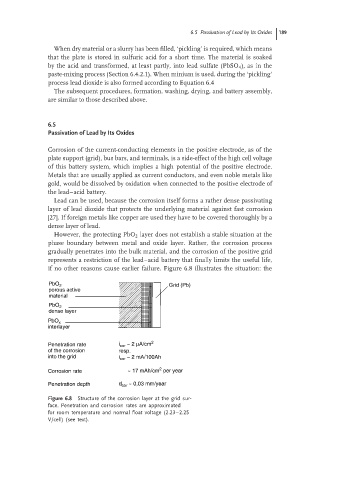
if no other reasons cause earlier failure. Figure 6.8 illustrates the situation: the
PbO 2 Grid (Pb)
porous active
material
PbO 2
dense layer
PbO x
interlayer
Penetration rate i cor ~ 2 µA/cm 2
of the corrosion resp.
into the grid i cor ~ 2 mA/100Ah
2
Corrosion rate ~ 17 mAh/cm per year
Penetration depth d cor ~ 0,03 mm/year
Figure 6.8 Structure of the corrosion layer at the grid sur-
face. Penetration and corrosion rates are approximated
for room temperature and normal float voltage (2.23–2.25
V/cell) (see text).