
Page 108 - Handbook of Biomechatronics
P. 108
104 Naser Mehrabi and John McPhee
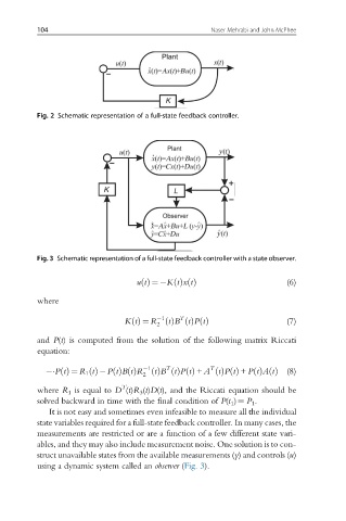
Fig. 2 Schematic representation of a full-state feedback controller.
Fig. 3 Schematic representation of a full-state feedback controller with a state observer.
utðÞ ¼ KtðÞxtðÞ (6)
where
1 T
t
KtðÞ ¼ R ðÞB tðÞPtðÞ (7)
2
and P(t) is computed from the solution of the following matrix Riccati
equation:
T
1
T
t
PtðÞ ¼ R 1 tðÞ PtðÞBtðÞR ðÞB tðÞPtðÞ + A tðÞPtðÞ + PtðÞAtðÞ (8)
2
T
where R 1 is equal to D (t)R 3 (t)D(t), and the Riccati equation should be
solved backward in time with the final condition of P(t 1 )¼ P 1 .
It is not easy and sometimes even infeasible to measure all the individual
state variables required for a full-state feedback controller. In many cases, the
measurements are restricted or are a function of a few different state vari-
ables, and they may also include measurement noise. One solution is to con-
struct unavailable states from the available measurements (y) and controls (u)
using a dynamic system called an observer (Fig. 3).