
Page 368 - Handbook of Biomechatronics
P. 368
362 Lilach Bareket et al.
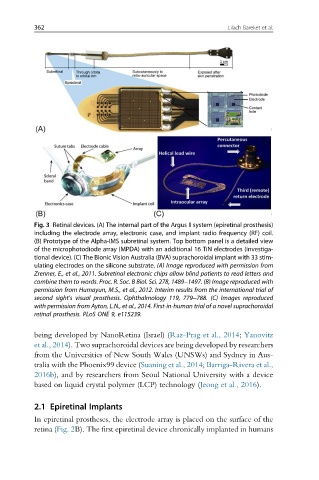
Fig. 3 Retinal devices. (A) The internal part of the Argus II system (epiretinal prosthesis)
including the electrode array, electronic case, and implant radio frequency (RF) coil.
(B) Prototype of the Alpha-IMS subretinal system. Top bottom panel is a detailed view
of the microphotodiode array (MPDA) with an additional 16 TiN electrodes (investiga-
tional device). (C) The Bionic Vision Australia (BVA) suprachoroidal implant with 33 stim-
ulating electrodes on the silicone substrate. (A) Image reproduced with permission from
Zrenner, E., et al., 2011. Subretinal electronic chips allow blind patients to read letters and
combine them to words. Proc. R. Soc. B Biol. Sci. 278, 1489–1497. (B) Image reproduced with
permission from Humayun, M.S., et al., 2012. Interim results from the international trial of
second sight’s visual prosthesis. Ophthalmology 119, 779–788. (C) Images reproduced
with permission from Ayton, L.N., et al., 2014. First-in-human trial of a novel suprachoroidal
retinal prosthesis. PLoS ONE 9, e115239.
being developed by NanoRetina (Israel) (Raz-Prag et al., 2014; Yanovitz
et al., 2014). Two suprachoroidal devices are being developed by researchers
from the Universities of New South Wales (UNSWs) and Sydney in Aus-
tralia with the Phoenix99 device (Suaning et al., 2014; Barriga-Rivera et al.,
2016b), and by researchers from Seoul National University with a device
based on liquid crystal polymer (LCP) technology (Jeong et al., 2016).
2.1 Epiretinal Implants
In epiretinal prostheses, the electrode array is placed on the surface of the
retina (Fig. 2B). The first epiretinal device chronically implanted in humans