
Page 389 - Handbook of Biomechatronics
P. 389
Current Advances in the Design of Retinal and Cortical Visual Prostheses 383
surface. The bone flap or synthetic material (acrylic) that is inserted instead of
the scalp area removed during exposure of the cortex should not apply any
pressure on the electrode array. Direct pressure on these grids may gradually
force the array to sink into the brain causing deformation and damage to the
cortex. If the active tip or shaft of the electrodes passes beyond the neurons of
the gray matter and enters the white matter, the electrodes will be non-
functional. In addition there is possible interference in cross-modal sensory
adaptation such as the reading of Braille which the blind person depends on
for activities of daily living (Lewis et al., 2015).
5.2 Parameters for Retinal and Cortical Stimulation
In 1968, Brindley and Lewin demonstrated that restoration of visual percep-
tion is possible through electrical stimulation of the visual cortex (Brindley
and Lewin, 1968). Nowadays, cortical and retinal neurostimulators are
emerging as a therapy (Lewis et al., 2016a). Despite the enormous progress
over the last decades, integration between the electrodes and the neural tis-
sue is still poor. While electrode locations in the visual cortex can directly
map visual perception (Lewis et al., 2015), at the retina, information is cod-
ified by the retinal neural network and transmitted to the brain via RGCs
(Koch, 2013). These anatomical and functional differences involve a need
for different stimulation strategies that target excitable cells more specifically.
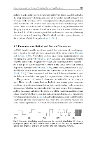
The parameters of electrical stimulation are critical in the nervous sys-
tem. These include: monophasic or biphasic stimulation; pulse durations;
anodic or cathodic stimulation (first or last); anodic scaling; pulse repetition
frequencies; whether the interpulse intervals have high or low impedance,
and the placement and size of the active area of the electrode, and the current
return path (or whether bipolar stimulation is used). Examples of stimulation
waveforms are illustrated in Fig. 5. Electrical stimulation itself (aside from the
electrodes’ physical presence) may also injure the surrounding neurons and
cause neurodegeneration. Electrochemical Faradic reactions can occur at the
Fig. 5 Common stimulation waveforms used in electrical stimulation. (A) shows a
monophasic pulse. (B) and (C) are biphasic pulses, anodic first and last respectively.
(D) is a train of pulses and (E) is an example of a high-frequency stimulus.