
Page 60 - Handbook of Biomechatronics
P. 60
54 Reva E. Johnson and Jonathon W. Sensinger
However, for many applications these disadvantages are outweighed by the
advantages, which include improved force rendering, improved force-
sensing fidelity, larger stable feedback gains (Whitney, 1977), improved
power densities using a catapult effect (Albu-Sch€affer et al., 2011), and sat-
uration of maximum impedance at high frequencies (Pratt and Williamson,
1995). Series elastic actuators reduce environmental impact forces for actu-
ators without substantial endpoint inertia (Zinn et al., 2004) (paragraph
excerpt from Sensinger et al., 2013).
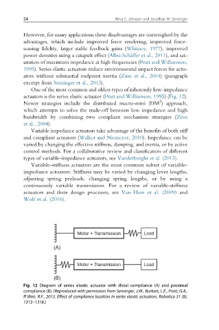
One of the most common and oldest types of inherently low-impedance
actuators is the series elastic actuator (Pratt and Williamson, 1995)(Fig. 12).
2
Newer strategies include the distributed macro-mini (DM ) approach,
which attempts to solve the trade-off between low impedance and high
bandwidth by combining two compliant mechanism strategies (Zinn
et al., 2004).
Variable impedance actuators take advantage of the benefits of both stiff
and compliant actuators (Walker and Niemeyer, 2010). Impedance can be
varied by changing the effective stiffness, damping, and inertia, or by active
control methods. For a collaborative review and classification of different
types of variable-impedance actuators, see Vanderborght et al. (2013).
Variable-stiffness actuators are the most common subset of variable-
impedance actuators. Stiffness may be varied by changing lever lengths,
adjusting spring preloads, changing spring lengths, or by using a
continuously variable transmission. For a review of variable-stiffness
actuators and their design processes, see Van Ham et al. (2009) and
Wolf et al. (2016).
Motor + Transmission Load
(A)
Motor + Transmission Load
(B)
Fig. 12 Diagram of series elastic actuator with distal compliance (A) and proximal
compliance (B). (Reproduced with permission from Sensinger, J.W., Burkart, L.E., Pratt, G.A.,
ff Weir, R.F., 2013. Effect of compliance location in series elastic actuators. Robotica 31 (8),
1313–1318.)