
Page 273 - Handbook of Civil Engineering Calculations, Second Edition
P. 273
2.58 REINFORCED AND PRESTRESSED CONCRETE ENGINEERING AND DESIGN
2. Compute the stresses at midspan due to the beam weight
2
Thus, M w ( /8)(83)(20) (12) 49,800 in.·lb (5626.4 N·m); f bw 49,800/133
1
374 lb/sq.in. ( 2578.7 kPa); f tw 374 lb/sq.in. (2578.7 kPa).
3. Set the critical stresses equal to their allowable values to
secure the allowable unit superimposed load
Use Fig. 32 or 33 as a guide. At support: f bi 2400 lb/sq.in. ( 16,548 kPa); f ti 190
lb/sq.in. ( 1310.1 kPa); at midspan, f bf 0.85(2400) 374 f bs 425 lb/sq.in.
( 2930.4 kPa); f tf 0.85( 190) 374 f ts 2250 lb/sq.in. ( 15,513.8 kPa). Also,
f bs 2091 lb/sq.in. ( 14,417.4 kPa); f ts 2038 lb/sq.in. ( 14,052 kPa).
Since the superimposed-load stresses at top and bottom will be numerically equal, the
latter value governs the beam capacity. Or w s w w , f ts /f tw 83(2038/374) 452 lb/lin ft
(6596.4 N/m).
4. Find F i,max and its eccentricity
The value of w s was found by setting the critical value of f ti and of f tf equal to their re-
spective allowable values. However, since S b is excessive for the load w s , there is flexibil-
ity with respect to the stresses at the bottom. The designer may set the critical value of ei-
ther f bi or f bf equal to its allowable value or produce some intermediate condition. As
shown by the calculations in step 3, f bf may vary within a range of 2091 2038 53
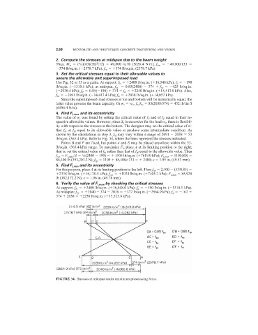
lb/sq.in. (365.4 kPa). Refer to Fig. 34, where the lines represent the stresses indicated.
Points B and F are fixed, but points A and E may be placed anywhere within the 53-
lb/sq.in. (365.4-kPa) range. To maximize F i , place A at its limiting position to the right;
that is, set the critical value of f bi rather than that of f bf equal to the allowable value. Then
f cai F i,max /A /2(2400 190) 1105 lb/sq.in. ( 7619.0 kPa); F i,max 1105(80)
1
88,400 lb (393,203.2 N); f bp 1105 88,400e/133 2400; e 1.95 in. (49.53 mm).
5. Find F i,min and its eccentricity
For this purpose, place A at its limiting position to the left. Then f bp 2,400 (53/0.85)
2338 lb/sq.in. ( 16,120.5 kPa); f cai 1074 lb/sq.in. ( 7405.2 kPa); F i,min 85,920
lb (382,172.2 N); e 1.96 in. (49.78 mm).
6. Verify the value of F i,max by checking the critical stresses
At support: f bi 2400 lb/sq.in. ( 16,548.0 kPa); f ti 190 lb/sq.in. ( 1310.1 kPa).
At midspan: f bf 2040 374 2038 372 lb/sq.in. ( 2564.9 kPa); f tf 162
374 2038 2250 lb/sq.in. ( 15,513.8 kPa).
FIGURE 34. Stresses at midspan under maximum prestressing force.