
Page 162 - Handbook of Electrical Engineering
P. 162
SWITCHGEAR AND MOTOR CONTROL CENTRES 145
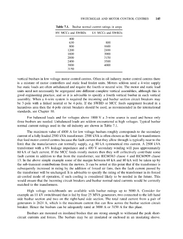
Table 7.1. Busbar normal current ratings in amps
HV MCCs and SWBDs LV MCCs and SWBDs
400
630 800
800 1600
1200 2400
1600 3000
2000 3150
2400 3500
3000 4000
3150
vertical busbars in low voltage motor control centres. Often in oil industry motor control centres there
is a mixture of motor controllers and static load feeder units. Motors seldom need a 4-wire supply
but static loads are often unbalanced and require the fourth or neutral wire. The motor and static load
units need not necessarily be segregated into different complete vertical assemblies, although this is
good engineering practice, and so it is advisable to specify a fourth vertical busbar in each vertical
assembly. When a 4-wire system is required the incoming and busbar section circuit breakers may
be 3-pole with a linked neutral or be 4-pole. If the SWBD or MCC feeds equipment located in a
hazardous area then the 4-pole circuit breakers should be used, as recommended in the international
standards, see Chapter 10.
For balanced loads and for voltages above 1000 V a 3-wire source is used and hence only
three busbars are needed. Unbalanced loads are seldom encountered at high voltages. Typical busbar
normal current ratings used in the oil industry are shown in Table 7.1.
The maximum value of 4000 A for low voltage busbars roughly corresponds to the secondary
current of a fully loaded 2500 kVA transformer. 2500 kVA is often chosen as the limit for transformers
that feed motor control centres because the fault current that they allow through is typically near to the
limit that the manufacturers can normally supply, e.g. 80 kA symmetrical rms current. A 2500 kVA
transformer with a 6% leakage impedance and a 400 V secondary winding will pass approximately
60 kA of fault current. If the MCC feeds mostly motors then they will collectively contribute some
fault current in addition to that from the transformer, see IEC60363 clause 4 and IEC60909 clause
13. In the above simple example some of the margin between 60 kA and 80 kA will be taken up by
the sub-transient contributions from the motors. It can be noted at this point that if the transformer is
subsequently increased in rating by the addition of forced air fans, then the fault current passed by
the transformer will be unchanged. It is advisable to specify the rating of the transformer in its forced
air-cooled mode of operation, if such cooling is considered likely to be needed in the future. This
would ensure that the incoming circuit breakers and busbar normal rated currents would be correctly
matched to the transformers.
High voltage switchboards are available with busbar ratings up to 5000 A. Consider for
example an 11 kV switchboard that is fed by four 25 MVA generators, two connected to the left-hand
side busbar section and two on the right-hand side section. The total rated current from a pair of
generators is 2624 A, which is the maximum current that can flow across the busbar section circuit
breaker. Hence the busbars can be adequately rated at 3000 A or 3150 A for this plant.
Busbars are mounted on insulated bushes that are strong enough to withstand the peak short-
circuit currents and forces. The busbars may be air insulated or enclosed in an insulating sleeve.