
Page 301 - Handbook of Electrical Engineering
P. 301
FAULT CALCULATIONS AND STABILITY STUDIES 287
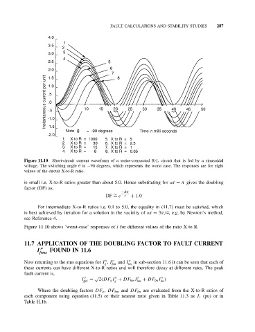
Figure 11.10 Short-circuit current waveform of a series-connected R-L circuit that is fed by a sinusoidal
voltage. The switching angle θ is −90 degrees, which represents the worst case. The responses are for eight
values of the circuit X-to-R ratio.
is small i.e. X-to-R ratios greater than about 5.0. Hence substituting for ωt = π gives the doubling
factor (DF) as,
−Rπ
∼
DF = e x + 1.0
For intermediate X-to-R ratios i.e. 0.1 to 5.0, the equality in (11.7) must be satisfied, which
is best achieved by iteration for a solution in the vacinity of ωt = 3π/4, e.g. by Newton’s method,
see Reference 4.
Figure 11.10 shows ‘worst-case’ responses of i for different values of the ratio X to R.
11.7 APPLICATION OF THE DOUBLING FACTOR TO FAULT CURRENT
I FOUND IN 11.6
frms
Now returning to the rms equations for I , I and I in sub-section 11.6 it can be seen that each of
g hm lm
these currents can have different X-to-R ratios and will therefore decay at different rates. The peak
fault current is,
√
I = 2(DF g I + DF hm I + DF lm I )
fpk g hm lm
Where the doubling factors DF g , DF hm and DF lm are evaluated from the X-to-R ratios of
each component using equation (11.5) or their nearest ratio given in Table 11.3 as I 1 (pu) or in
Table H.1b.