
Page 305 - Handbook of Electrical Engineering
P. 305
FAULT CALCULATIONS AND STABILITY STUDIES 291
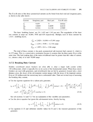
The X-to-R ratios of the three symmetrical currents can be found from their real and imaginary parts,
as shown in the table below:-
Current Imaginary part Real part X-to-R ratio
I g 9.639 0 infinity
I 3.0849 0.4659 6.6214
hm
I 0.3321 0.1130 2.9389
lm
The three ‘doubling factors’ are 2.0, 1.622 and 1.343 per unit. The magnitudes of the three
rms currents in amps are 16,864, 5458 and 614 respectively. Multiply each of these currents by
1.414 × doubling factor,
I gpk = 2.828 × 16,864 = 47,691 amps
I = 2.294 × 5458 = 12, 518 amps
hmpk
I = 1.899 × 614 = 1166 amps
lmpk
The total of these currents is the peak asymmetrical sub-transient fault current I which is
pk
61,375 amps. This is a conservative summation because it assumes that the three peaks occur at the
same time. The fault making duty of the main switchboard must be greater than this value of current,
i.e., choose a duty of at least 70,000 amps.
11.7.2 Breaking Duty Current
Modern switchboard circuit breakers are often able to clear a major fault current within
120 milliseconds, which is typically five or six cycles of the fundamental current. When these circuit
breakers are used with generators, and switchboards that are fed by generators located only a short
distance away, the decay of the sub-transient current merges with the decay of the transient current.
Even at 120 milliseconds the current may have a substantial value. There are several ways of assessing
the breaking duty current,
• Use the rigorous equations for a salient pole generator,
1 1 1 −t 1 1 −t (X d + X q ) −t
i fa = V ˆ + − e T d + − e T d cos(ωt + θ) − V ˆ e Ta
X d X d X d X d X d 2X d X
q
−t
X q − X d
cos θ − V ˆ e Ta cos(2ωt + θ) (11.8)
2X d X q
See sub-sections 3.4 and 7.2.7 for an explanation of the variables and parameters.
• Use the above equation but ignore the sub-transient terms, thereby leaving,
1 1 1
−t
i fa = V ˆ + − e T d cos(ωt + θ) (11.9)
X d X d X d
• Use equation (11.5) and substitute suitable values for R and L the transient parameters of the
generator.