
Page 35 - Handbook of Electrical Engineering
P. 35
14 HANDBOOK OF ELECTRICAL ENGINEERING
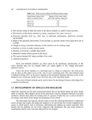
Table 1.11. Ratio of motor rating to the driven machine rating
Approximate rating of the Margin of the motor rating
motor or machine (kW) above the machine rating (%)
Up to 15 125
16.0 to 55 115
Above 55 110
• The absolute rating of either the motor or the driven machine i.e. small or large machines.
• The function of the driven machine e.g. pump, compressor, fan, crane, conveyor.
• Expected operating level e.g. often near to maximum performance, short-term overload-
ing permitted.
• Shape of the operating characteristic of the machine e.g. pressure (head) versus liquid flow rate in
a pump.
• Change in energy conversion efficiency of the machine over its working range.
• Machine is driven at nearly constant speed.
• Machine is driven by a variable speed motor.
• Harmonic currents will be present in the motor.
• The nearest standard kW rating available of the motor.
• Ambient temperature.
Some rule-of-thumb methods are often stated in the purchasing specifications of the
motor–machine unit, see for example Table 1.11, which applies to low voltage three-phase
induction motors.
Where the driven machine is a centrifugal type i.e. pump or compressor, the shaft power
may be taken as that which occurs at the ‘end of curve’ operating point. This rule-of-thumb point
is defined as being 125% of the power required at the maximum operating efficiency point on the
designed curve of pressure (head) versus fluid flow rate, at the rated shaft speed.
These rule-of-thumb methods can be used to check the declared performance and ratings from
a machine manufacturer.
1.7 DEVELOPMENT OF SINGLE-LINE DIAGRAMS
Single-line diagrams are the most essential documents that are developed during the detail design
phase of a project. They identify almost all the main items of power equipment and their associated
ancillaries. Initially they define the starting point of a project. Finally they are a concise record of
the design, from which all the design and purchasing work evolved.
The final single-line diagrams should contain at least the following information. Complicated
power systems may require the single-line diagrams to be sub-divided into several companion dia-
grams, in which aspects such as protection, interlocking and earthing are treated separately. This
ensures that the diagrams are not overly congested with information. The end results should be
unambiguous and be easily read and understood by the recipient.