
Page 30 - Handbook of Electrical Engineering
P. 30
ESTIMATION OF PLANT ELECTRICAL LOAD 9
Any allowance required for future load growth should be included in the power consumption calcula-
tions. This two-part approach is often referred to as the ‘N − 1 philosophy’, where N is the number
of installed generators or feeders. The philosophy is that under normal operating conditions in a fully
load plant N − 1 generators or feeders should be sufficient to supply the load at a reasonably high
load factor.
Let P l = power consumption required at the site ambient conditions
P g = rated power of each generator or feeder at the site ambient conditions
F o = overload power in % when one generator or feeder is suddenly switched out of service
F i = load factor in % of each generator or feeder before one is switched out of service
N = number of installed generators or feeders. N is usually between 4 and 6 for an
economical design of a generating plant and 2 or 3 for feeders.
P l and P g are usually the known variables, with F i and F o being the unknown variables.
Several feasible ratings of P g may be available and the value of N may be open to choice. A good
choice of P g and N will ensure that the normally running load factor is high i.e. between 70% and
85%, whilst the post-disturbance overload on the remaining generators or feeders will not be so high
that they trip soon after the disturbance, i.e. less than 125%.
The initial load factor can be found as,
100P l
F i = %
P g (N − 1)
The post-disturbance overload can be found as,
100P l
F o = %
P g (N − 2)
If it is required that F i is chosen for the design such that F = 100% and no overload occurs
then let F be called F i100 and so,
(N − 2)100
F i100 = for no overloading.
N − 1
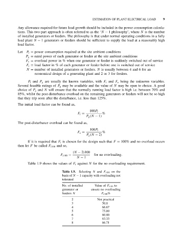
Table 1.9 shows the values of F i against N for the no overloading requirement.
Table 1.9. Selecting N and F i100 on the
basis of N − 1 capacity with overloading not
tolerated
No. of installed Value of F i100 to
generator or ensure no overloading
feeders N F i100 %
2 Not practical
3 50.0
4 66.67
5 75.00
6 80.00
7 83.33
8 86.71