
Page 29 - Handbook of Electrical Engineering
P. 29
8 HANDBOOK OF ELECTRICAL ENGINEERING
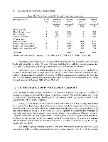
Table 1.8. Master load schedule for the high voltage main switchboard
Description of load No. of Nameplate Continuous Intermittent Standby
units ratings of power power power
each unit consumed consumed consumed
(kW) (kW) (kW) (kW)
HV motor loads
Main oil expert pumps 3 650 1300 0 650
Gas compressor 4 500 1500 0 500
Seawater lift pumps 4 450 1350 0 450
LV motor loads
Feeder to drilling 1 0 2700 2400 1000
Feeder to LV process MCC 2 0 1652 319 1077
Feeder to LV utilities MCC 1 0 1013 320 633
Feeder to LV emergency MCC 1 0 168 179 58
Sub-totals 9983 3218 4368
Totals for the main generator to supply = (1.0 × 9983) + (0.5 × 3218) + (0.1 × 4368) = 12,029 kW
During the detail design phase of the project the load schedules will be modified and additional
loads will inevitably be added. At least 10% extra load should be added to the first estimate i.e.
1203 kW. The total when rounded-up to the nearest 100 kW would be 13,300 kW.
Sufficient generators should be installed such that those that are necessary to run should be
loaded to about 80 to 85% of their continuous ratings, at the declared ambient temperature. This
subject is discussed in more detail in sub-section 1.3. If four generators are installed on the basis that
one is a non-running standby unit, then three must share the load. Hence a reasonable power rating
for each generator is between 5216 kW and 5542 kW.
1.3 DETERMINATION OF POWER SUPPLY CAPACITY
After the load has been carefully estimated it is necessary to select the ratings and numbers of
generators, or main incoming feeders from a power utility company. Occasionally a plant may require
a combination of generators and incoming feeders e.g. refinery, which may operate in isolation or in
synchronism with the utility company.
Usually a plant has scope for expansion in the future. This scope may be easy to determine
or it may have a high degree of uncertainty. The owner may have strong reasons to economise
initially and therefore be only willing to install enough capacity to meet the plant requirements in
the first few years of operation. If this is the case then it is prudent to ensure that the switchgear in
particular has adequate busbar normal current rating and fault current rating for all future expansion.
The main circuit breakers should be rated in a similar manner. If the switchgear is rated properly at
the beginning of a project, then all future additions should be relatively easy to achieve in a practical
and economical manner. Such an approach also leads to a power system that is easy to start up,
operate and shut down.
The supply capacity normally consists of two parts. One part to match the known or initial
consumption and a second part to account for keeping a spare generator or feeder ready for service.