
Page 429 - Handbook of Electrical Engineering
P. 429
418 HANDBOOK OF ELECTRICAL ENGINEERING
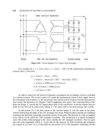
Figure 15.6 Circuit diagram of a 12-pulse thyristor bridge.
◦
For example, let i 1 = I sin ωt and i 2 = I sin(ωt − 120 ) be the fundamental instantaneous
currents, then i 12 becomes,
◦
i 12 = I(sin ωt − sin(ωt − 120 ))
◦
◦
= I(sin ωt − sin ωt cos(−120 ) − cos ωt sin(−120 ))
= I(sin ωt + 0.866 cos ωt + 0.5sin ωt)
= I(+1.5sin ωt + 0.866 cos ωt)
√ ◦
= 3I sin(ωt + 30 )
In order to obtain the full benefit of harmonic cancellation the two bridges must be controlled
in a common manner. The control system will enable the fundamental current in both supply lines of
the same phase to be in-phase, i.e. the star primary line current must be in-phase with the delta primary
line current. See Reference 12, Chapter 3 which emphasises this aspect. The controlled firing of the
◦
delta-star bridge T u cancels the 30 degree phase shift of the transformer. From the Fourier analysis
◦
point of view this can be achieved by adding a + 30 phase shift to the delta primary line current.
In sub-section 15.3.1 the line current of the star-star bridge T l was the same as the phase
◦
current, both having the shape of the 120 rectangle wave form. When the phase currents are combined
to produce the delta line current the waveform consists of two parts. The first part is a full, rectangular
◦
wave, which can be called the ‘180 rectangle waveform’. The second part is a narrow rectangular
◦
◦
wave. The width of this rectangle is 60 , hence call this the ‘60 rectangle waveform’. The two parts
have the same magnitude, which is 1.0 per unit for the analysis. In both waveforms the rectangles
are centred at π/2and3π/2, as described in sub-section 15.3.1. The harmonic coefficients for the