
Page 432 - Handbook of Electrical Engineering
P. 432
HARMONIC VOLTAGES AND CURRENTS 421
◦
◦
The effect of the commutation angle u on the 180 ,60 and supply current waveforms is the
◦
same as found in sub-section 15.3.2 for the 120 waveform. Therefore each coefficient b n becomes,
un
2b n
b nu = sin
un 2
◦
Figures 15.7 and 15.8 show the following waveforms for u = 5 for the first 25 and 43
harmonics included, some being naturally zero.
◦
• Star primary line current or 120 waveform.
◦
◦
• Delta primary line current or the sum of the 180 and 60 waveforms.
• Total primary line current.
15.4 INVERTERS
15.4.1 Basic Method of Operation
Inversion is the process by which a DC voltage is changed into an AC voltage by the use of a set of
switches. The following illustrates the method of operation of a simple single-phase ‘square-wave’
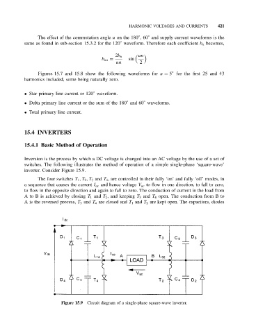
inverter. Consider Figure 15.9.
The four switches T 1 ,T 2 ,T 3 and T 4 , are controlled in their fully ‘on’ and fully ‘off’ modes, in
a sequence that causes the current I ac and hence voltage V ac to flow in one direction, to fall to zero,
to flow in the opposite direction and again to fall to zero. The conduction of current in the load from
A to B is achieved by closing T 1 and T 2 , and keeping T 3 and T 4 open. The conduction from B to
A is the reversed process, T 3 and T 4 are closed and T 1 and T 2 are kept open. The capacitors, diodes
Figure 15.9 Circuit diagram of a single-phase square-wave inverter.