
Page 435 - Handbook of Electrical Engineering
P. 435
424 HANDBOOK OF ELECTRICAL ENGINEERING
For motors that normally operate at slips in the order of 0.5% to 3.0% the values of s n for n,
greater than unity are approximately given by,
n − 1
s n for n = 7, 13, 19 etc.
n
= 0.8571, 0.9231, 0.9474 etc.
n + 1
s n for n = 5, 11, 17 etc.
n
= 1.2, 1.0909, 1.0588 etc.
The rotor resistance that represents the winding and the load is R 2 /s 1 for the fundamental.
For the harmonic resistance to be found simply replace s 1 by s n .
15.4.3.1 Worked example
A 250 kW three-phase, four-pole, 50 Hz, 415 V, induction motor is fed from a voltage source inverter.
The motor has the following parameters for its star-wound windings. Find the currents and air-gap
voltage in the circuit.
R 1 Stator resistance 0.0053 ohms
X 1 Stator leakage reactance 0.0470 ohms
R 2 Rotor resistance at full-load 0.0045 ohms
X 2 Rotor reactance at full-load 0.1113 ohms
X m Magnetising reactance 2.9310 ohms
s 1 Full-load slip 0.00738 pu
Full-load efficiency 0.983 pu
Full-load power factor 0.902 pu
Full-load current 392.26 amps
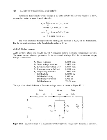
The equivalent circuit fed from a Thevenin voltage source is shown in Figure 15.11.
Figure 15.11 Equivalent circuit of an induction motor when fed from a voltage source that contains harmonics.