
Page 78 - Handbook of Electrical Engineering
P. 78
GAS TURBINE DRIVEN GENERATORS 57
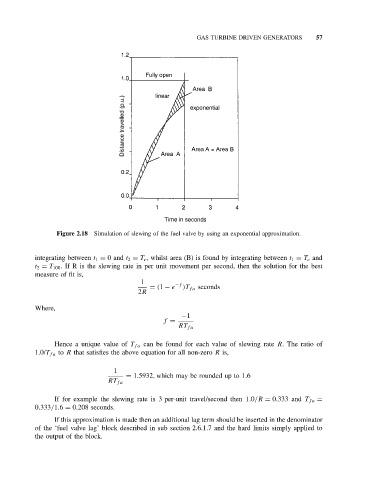
Figure 2.18 Simulation of slewing of the fuel valve by using an exponential approximation.
integrating between t 1 = 0and t 2 = T e , whilst area (B) is found by integrating between t 1 = T e and
t 2 = T 100 . If R is the slewing rate in per unit movement per second, then the solution for the best
measure of fit is,
1 −f
= (1 − e )T fa seconds
2R
Where,
−1
f =
RT fa
Hence a unique value of T fa can be found for each value of slewing rate R. The ratio of
1.0/T fa to R that satisfies the above equation for all non-zero R is,
1
= 1.5932, which may be rounded up to 1.6
RT fa
If for example the slewing rate is 3 per-unit travel/second then 1.0/R = 0.333 and T fa =
0.333/1.6 = 0.208 seconds.
If this approximation is made then an additional lag term should be inserted in the denominator
of the ‘fuel valve lag’ block described in sub section 2.6.1.7 and the hard limits simply applied to
the output of the block.