
Page 320 - Handbook of Materials Failure Analysis
P. 320
5 Laminar Particles 317
50µm 50µm
(a) (b)
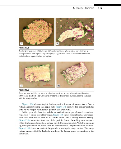
FIGURE 13.5
The laminar particles (200 ) from different machines: (a) a laminar particle from a
rolling element bearing in a paper mill; (b) a big laminar particle and the small laminar
particles from a gearbox in a pulp plant.
50µm 50µm
(a) (b)
FIGURE 13.6
The front side and the backside of a laminar particles from a rolling element bearing
(200 ): (a) the front side with some striations on the smooth surface; (b) the backside
with the rough surface.
Figure 13.5a shows a typical laminar particle from an oil sample taken from a
rolling element bearing in a paper mill. Figure 13.5 displays the laminar particles
from an oil sample taken from a gearbox in a pulp plant.
In filtergram, the front side and the backside of a wear particle can be examined,
respectively, with a special technique. Figure 13.6 shows both sides of a laminar par-
ticle. This particle was from an oil sample taken from a rolling element bearing.
Figure 13.6a shows the front side of the particle. Due to the rolling over, the trace
of the striations on the particle surface can still be distinguished. With the magnetic
tip, wear particle can be turned over. So the backside of the particle can be revealed.
Figure 13.6b is the backside of the particle, showing the rough surface. The rough
feature suggests that the backside was from the fatigue crack propagation in the
subsurface.