
Page 296 - Handbook of Plastics Technologies
P. 296
ELASTOMERS
4.88 CHAPTER 4
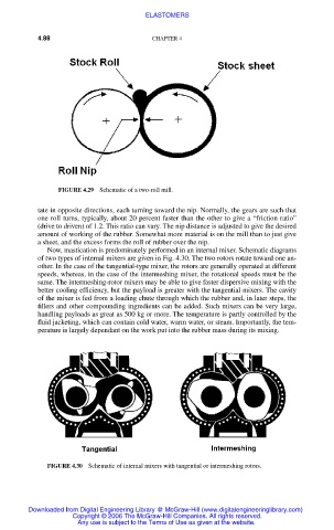
FIGURE 4.29 Schematic of a two-roll mill.
tate in opposite directions, each turning toward the nip. Normally, the gears are such that
one roll turns, typically, about 20 percent faster than the other to give a “friction ratio”
(drive to driven) of 1.2. This ratio can vary. The nip distance is adjusted to give the desired
amount of working of the rubber. Somewhat more material is on the mill than to just give
a sheet, and the excess forms the roll of rubber over the nip.
Now, mastication is predominately performed in an internal mixer. Schematic diagrams
of two types of internal mixers are given in Fig. 4.30. The two rotors rotate toward one an-
other. In the case of the tangential-type mixer, the rotors are generally operated at different
speeds, whereas, in the case of the intermeshing mixer, the rotational speeds must be the
same. The intermeshing-rotor mixers may be able to give faster dispersive mixing with the
better cooling efficiency, but the payload is greater with the tangential mixers. The cavity
of the mixer is fed from a loading chute through which the rubber and, in later steps, the
fillers and other compounding ingredients can be added. Such mixers can be very large,
handling payloads as great as 500 kg or more. The temperature is partly controlled by the
fluid jacketing, which can contain cold water, warm water, or steam. Importantly, the tem-
perature is largely dependant on the work put into the rubber mass during its mixing.
FIGURE 4.30 Schematic of internal mixers with tangential or intermeshing rotors.
Downloaded from Digital Engineering Library @ McGraw-Hill (www.digitalengineeringlibrary.com)
Copyright © 2006 The McGraw-Hill Companies. All rights reserved.
Any use is subject to the Terms of Use as given at the website.