
Page 156 - Handbook of Structural Steel Connection Design and Details
P. 156
Design of Connections for Axial, Moment, and Shear Forces
Design of Connections for Axial, Moment, and Shear Forces 141
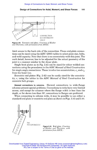
Figure 2.42 Eccentric end plate. (Courtesy of Kloiber
and Thornton, with permission from ASCE.)
limit access to the back side of the connection. These end-plate connec-
tions can be sized using the AISC (2005) tables to select plate size, bolts,
and weld capacity. Note that there is no eccentricity with this joint. The
weld detail, however, has to be adjusted for the actual geometry of the
joint in a manner similar to the shear plate.
Single bent plates as in Fig. 2.41 can be sized for either welded con-
nections using the procedures in the AISC Manual of Steel Construction
for single angle connections. These involve two eccentricities, e and e ,
1 2
from the bend line.
Eccentric end plates (Fig. 2.42) can be easily sized for the eccentric-
ity, e, using the tables in the AISC Manual of Steel Construction for
eccentric bolt groups.
Skewed connections to columns. Skewed connections to wide-flange
columns present special problems. Connections to webs have very limited
access, and except for columns where the flange width is less than the
o
depth, or for skews less than 30 , connections to flanges are preferred.
When connecting to column webs, it may be possible to use either a
standard end plate or eccentric end plate as shown in Figs. 2.43 and 2.44.
Figure 2.43 End plate. (Courtesy
of Kloiber and Thornton, with
permission from ASCE.)
Downloaded from Digital Engineering Library @ McGraw-Hill (www.accessengineeringlibrary.com)
Copyright © 2009 The McGraw-Hill Companies. All rights reserved.
Any use is subject to the Terms of Use as given at the website.