
Page 153 - Handbook of Structural Steel Connection Design and Details
P. 153
Design of Connections for Axial, Moment, and Shear Forces
138 Chapter Two
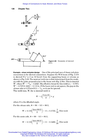
Figure 2.38 Geometry of skewed
joint.
Example—shear end plate design. One of the principal uses of shear end-plate
connections is for skewed connections. Suppose the W16 beam of Fig. 2.37b
1 o
is skewed 9 / 2 (a 2 on 12 bevel) from the supporting beam or column as
shown in Fig. 2.38. The nominal weld size is that determined from the analy-
sis with the plate perpendicular to the beam web (Fig. 2.38a). This is denoted
Wr , where Wr 2.6 / 0.1625. The effective throat for this weld is t 0.7071
16
e
Wr 0.707(0.1625) 0.115 in. If the beam web is cut square, the gap on the
1
obtuse side is 0.275sin(9.5) / , so it can be ignored.
16
The weld size, W, for a skewed weld is
2 sin
W 5 t e a b 1 g
2
where is the dihedral angle.
For the obtuse side, 90 9.5 99.5,
2sins99.5d 3
W 5 0.115a b 1 0 5 0.1755; fillet weld
2 16
For the acute side, 90 9.5 80.5,
2sins80.5d 3
W 5 0.115a b 1 0 5 0.1486; fillet weld
2 16
Downloaded from Digital Engineering Library @ McGraw-Hill (www.accessengineeringlibrary.com)
Copyright © 2009 The McGraw-Hill Companies. All rights reserved.
Any use is subject to the Terms of Use as given at the website.