
Page 149 - Handbook of Structural Steel Connection Design and Details
P. 149
Design of Connections for Axial, Moment, and Shear Forces
134 Chapter Two
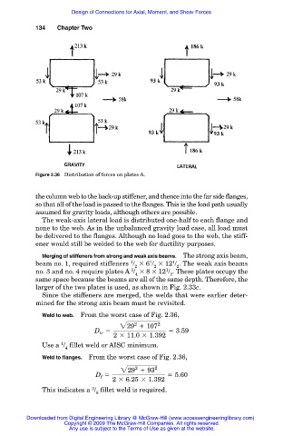
Figure 2.36 Distribution of forces on plates A.
the column web to the back-up stiffener, and thence into the far side flanges,
so that all of the load is passed to the flanges. This is the load path usually
assumed for gravity loads, although others are possible.
The weak-axis lateral load is distributed one-half to each flange and
none to the web. As in the unbalanced gravity load case, all load must
be delivered to the flanges. Although no load goes to the web, the stiff-
ener would still be welded to the web for ductility purposes.
Merging of stiffeners from strong and weak axis beams. The strong axis beam,
1
1
1
beam no. 1, required stiffeners / 6 / 12 / . The weak axis beams
2 2 2
3
1
no. 3 and no. 4 require plates A / 8 12 / . These plates occupy the
4 2
same space because the beams are all of the same depth. Therefore, the
larger of the two plates is used, as shown in Fig. 2.33c.
Since the stiffeners are merged, the welds that were earlier deter-
mined for the strong axis beam must be revisited.
Weld to web. From the worst case of Fig. 2.36,
2
229 1 107 2
D 5 5 3.59
w
2 3 11.0 3 1.392
1
Use a / fillet weld or AISC minimum.
4
Weld to flanges. From the worst case of Fig. 2.36,
2
229 1 93 2
D 5 5 5.60
f
2 3 6.25 3 1.392
3
This indicates a / fillet weld is required.
8
Downloaded from Digital Engineering Library @ McGraw-Hill (www.accessengineeringlibrary.com)
Copyright © 2009 The McGraw-Hill Companies. All rights reserved.
Any use is subject to the Terms of Use as given at the website.