
Page 178 - Handbook of Structural Steel Connection Design and Details
P. 178
Design of Connections for Axial, Moment, and Shear Forces
Design of Connections for Axial, Moment, and Shear Forces 163
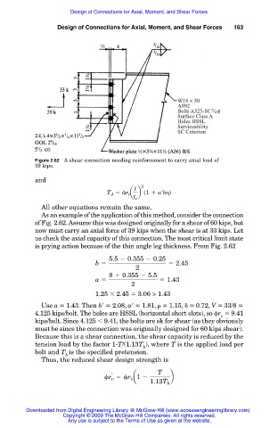
Figure 2.62 A shear connection needing reinforcement to carry axial load of
39 kips.
and
t 2
T d 5 r t a b s1 1 r d
t c
All other equations remain the same.
As an example of the application of this method, consider the connection
of Fig. 2.62. Assume this was designed originally for a shear of 60 kips, but
now must carry an axial force of 39 kips when the shear is at 33 kips. Let
us check the axial capacity of this connection. The most critical limit state
is prying action because of the thin angle leg thickness. From Fig. 2.62
5.5 2 0.355 2 0.25
b 5 5 2.45
2
8 1 0.355 2 5.5
a 5 5 1.43
2
1.25 2.45 3.06 > 1.43
Use a 1.43. Then b 2.08, a 1.81, 1.15, 0.72, V 33/8
4.125 kips/bolt. The holes are HSSL (horizontal short slots), so r 9.41
v
kips/bolt. Since 4.125 9.41, the bolts are ok for shear (as they obviously
must be since the connection was originally designed for 60 kips shear).
Because this is a shear connection, the shear capacity is reduced by the
tension load by the factor 1-T/(1.13T ), where T is the applied load per
b
bolt and T is the specified pretension.
b
Thus, the reduced shear design strength is
T
5 r a1 2
r v v b
1.13T b
Downloaded from Digital Engineering Library @ McGraw-Hill (www.accessengineeringlibrary.com)
Copyright © 2009 The McGraw-Hill Companies. All rights reserved.
Any use is subject to the Terms of Use as given at the website.