
Page 180 - Handbook of Structural Steel Connection Design and Details
P. 180
Design of Connections for Axial, Moment, and Shear Forces
Design of Connections for Axial, Moment, and Shear Forces 165
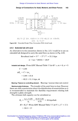
Figure 2.63 Extended Single Plate Connection With Axial Load.
2.5.3 Extended tab with axial
An alternative to the connection shown in Sec. 2.5.1 would be to use an
extended tab designed to carry the axial force as shown in Fig. 2.63.
2 0.5
Resultant load (V 2 T ) 51.1 kips
1
tan (39/33) 49.8°
Inelastic bolt design. From AISC Manual Table 7-7at 45° >, ex 6, n 5
C 2.88
R C r
n n
2.88 21.6
62.2 51.1 kips, ok
Bearing / Tearout on controlling element. Bearing / tearout does not control
Maximum plate thickness. The transfer of the axial force is clear. However
there are still uncertainties about the distribution of eccentricities so it
is recommended to maintain the ductility requirement relating bolt
strength to plate strength.
The ultimate bolt capacity can be calculated as
r s1.25d 21.6s1.25d
v n
R 5 5 5 36 kips/bolt
n
v 0.75
M R C (From AISC Manual Table 7-7 at 0°) >, C 17.1
n
36.0 17
Downloaded from Digital Engineering Library @ McGraw-Hill (www.accessengineeringlibrary.com)
Copyright © 2009 The McGraw-Hill Companies. All rights reserved.
Any use is subject to the Terms of Use as given at the website.