
Page 286 - Handbook of Structural Steel Connection Design and Details
P. 286
Welded Joint Design and Production
Welded Joint Design and Production 271
greatly increasing the portion of the column participating in the trans-
fer of moment. Significant experience was gained utilizing the haunches
for the repairs of the SAC-sponsored tests.
Reduced beam section connections. In this configuration, the cross sec-
tion of the beam is intentionally reduced within a segment to produce a
deliberate plastic hinge within the beam span, away from the column
face. One variant of this approach produces the so-called dog-bone profile.
Reduced section details offer the prospect of a low-cost connection
and increased performance out of detailing that is very similar to the
pre-Northridge connection. Control of material properties of the beam
will still be a major variable if this detail is used. Lateral bracing will
probably be required in the area of the reduced section to prevent buck-
ling, particularly at the bottom flange when loaded in compression.
Partially restrained connections. Several engineers and researchers
have suggested that partially restrained connection details will offer
a performance advantage over the special moment-resisting frames.
The relative merits of a partially restrained frame versus a rigid
frame are beyond the scope of this chapter. However, many engineers
immediately think of bolted PR connections when it is possible to uti-
lize welded connections for PR performance as well.
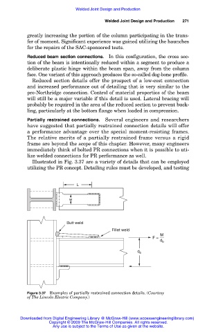
Illustrated in Fig. 3.37 are a variety of details that can be employed
utilizing the PR concept. Detailing rules must be developed, and testing
L
w
Butt weld
Fillet weld
M
F =
d b
d b
Figure 3.37 Examples of partially restrained connection details. (Courtesy
of The Lincoln Electric Company.)
Downloaded from Digital Engineering Library @ McGraw-Hill (www.accessengineeringlibrary.com)
Copyright © 2009 The McGraw-Hill Companies. All rights reserved.
Any use is subject to the Terms of Use as given at the website.