
Page 291 - Handbook of Structural Steel Connection Design and Details
P. 291
Partially Restrained Connections
276 Chapter Four
Tensile yielding
of bolt
Yield lines due
to bending
θ
Slip of bolts and
yielding in bearing
P
(b) Deformed configuration for angle.
M = P L
L
(a) Typical connection test specimen
θ
(c) Moment-rotation curve
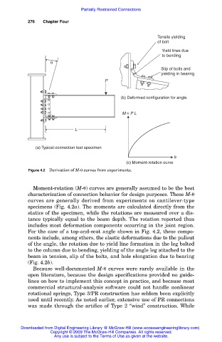
Figure 4.2 Derivation of M- curves from experiments.
Moment-rotation (M- ) curves are generally assumed to be the best
characterization of connection behavior for design purposes. These M-
curves are generally derived from experiments on cantilever-type
specimens (Fig. 4.2a). The moments are calculated directly from the
statics of the specimen, while the rotations are measured over a dis-
tance typically equal to the beam depth. The rotation reported thus
includes most deformation components occurring in the joint region.
For the case of a top-and-seat angle shown in Fig. 4.2, these compo-
nents include, among others, the elastic deformations due to the pullout
of the angle, the rotation due to yield line formation in the leg bolted
to the column due to bending, yielding of the angle leg attached to the
beam in tension, slip of the bolts, and hole elongation due to bearing
(Fig. 4.2b).
Because well-documented M- curves were rarely available in the
open literature, because the design specifications provided no guide-
lines on how to implement this concept in practice, and because most
commercial structural-analysis software could not handle nonlinear
rotational springs, Type 3/PR construction has seldom been explicitly
used until recently. As noted earlier, extensive use of PR connections
was made through the artifice of Type 2 “wind” construction. While
Downloaded from Digital Engineering Library @ McGraw-Hill (www.accessengineeringlibrary.com)
Copyright © 2009 The McGraw-Hill Companies. All rights reserved.
Any use is subject to the Terms of Use as given at the website.