
Page 293 - Handbook of Structural Steel Connection Design and Details
P. 293
Partially Restrained Connections
278 Chapter Four
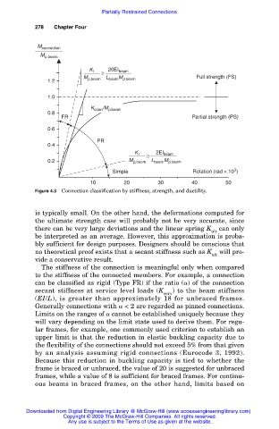
M connection
M p,beam
K i ≥ 20EI beam
M p,beam L beam M p,beam Full strength (FS)
1.2
1.0
K conn /M p,beam
0.8
FR Partial strength (PS)
0.6
PR
0.4
K i ≥ 2EI beam
0.2 M p,beam L beam M p,beam
3
Simple Rotation (rad × 10 )
10 20 30 40 50
Figure 4.3 Connection classification by stiffness, strength, and ductility.
is typically small. On the other hand, the deformations computed for
the ultimate strength case will probably not be very accurate, since
there can be very large deviations and the linear spring K can only
ult
be interpreted as an average. However, this approximation is proba-
bly sufficient for design purposes. Designers should be conscious that
no theoretical proof exists that a secant stiffness such as K will pro-
ult
vide a conservative result.
The stiffness of the connection is meaningful only when compared
to the stiffness of the connected members. For example, a connection
can be classified as rigid (Type FR) if the ratio ( ) of the connection
secant stiffness at service level loads (K ) to the beam stiffness
serv
(EI/L), is greater than approximately 18 for unbraced frames.
Generally connections with < 2 are regarded as pinned connections.
Limits on the ranges of cannot be established uniquely because they
will vary depending on the limit state used to derive them. For regu-
lar frames, for example, one commonly used criterion to establish an
upper limit is that the reduction in elastic buckling capacity due to
the flexibility of the connections should not exceed 5% from that given
by an analysis assuming rigid connections (Eurocode 3, 1992).
Because this reduction in buckling capacity is tied to whether the
frame is braced or unbraced, the value of 20 is suggested for unbraced
frames, while a value of 8 is sufficient for braced frames. For continu-
ous beams in braced frames, on the other hand, limits based on
Downloaded from Digital Engineering Library @ McGraw-Hill (www.accessengineeringlibrary.com)
Copyright © 2009 The McGraw-Hill Companies. All rights reserved.
Any use is subject to the Terms of Use as given at the website.