
Page 298 - Handbook of Structural Steel Connection Design and Details
P. 298
Partially Restrained Connections
Partially Restrained Connections 283
5 1.6
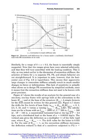
Deflection (wL 4 /384EI) 4 3 M (end) 1.2 Moment (wL 2 /12)
0.8
M (CL)
2
Deflection 0.4
1 0.0
0.01 0.1 1 10 100
α = Connection to beam stiffness ratio
Figure 4.6 Moments and deflections for a beam under a uniformly distributed
load with PR connections at its ends.
Similarly, for a range of 0 < < 0.3, the beam is essentially simply
supported. Note that the ranges given here were selected arbitrarily,
and that they will vary somewhat with the loading condition. This is
why, as was noted earlier in the discussion of connection stiffness, the
selection of limits for to separate FR, PR, and simple behavior are
not straightforward. It is important to note, however, that the hori-
zontal axis of Fig. 4.6 is logarithmic. This means that apparently
large changes in connection stiffness actually result in much smaller
changes in forces or deformations. This lack of sensitivity is actually
what allows us to design PR connections by simplified methods, since
it means that the connection stiffness does not need to be known with
great precision.
Figure 4.7 shows the results of an analysis for the general case of a
one-story, one-bay frame with springs both at the connections to the
beam (K ) and at the base of the structure (K ). A simple formula
conn base
for the drift cannot be written for this general case. Figure 4.7 shows
the drifts for five levels of base fixity ( K H /EI 0, 1,
base base e column
2.5, 5, 10, and ) versus a varying (K L/EI). The calcula-
beam conn
tions are for a frame with an I 2000 in , L 288 in, I 500
4
beam column
in ,|H 144 in, a concentrated horizontal load at the top of P 2.4
4
kips, and a distributed load on the beam of w 0.08333 kip/in. The
vertical axis gives the deflection as a multiplier ( ) of the fully rigid
case, where K K . The drift value for the latter is 0.025
conn base
in. For the case of K , as the connection stiffness decreases,
base
the deflection reduces to that of a cantilever subjected to P/2 (
Downloaded from Digital Engineering Library @ McGraw-Hill (www.accessengineeringlibrary.com)
Copyright © 2009 The McGraw-Hill Companies. All rights reserved.
Any use is subject to the Terms of Use as given at the website.