
Page 301 - Handbook of Structural Steel Connection Design and Details
P. 301
Partially Restrained Connections
286 Chapter Four
members, it is possible to adjust the stiffness to match that assumed
in design.
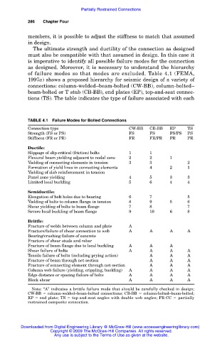
The ultimate strength and ductility of the connection as designed
must also be compatible with that assumed in design. In this case it
is imperative to identify all possible failure modes for the connection
as designed. Moreover, it is necessary to understand the hierarchy
of failure modes so that modes are excluded. Table 4.1 (FEMA,
1997a) shows a proposed hierarchy for seismic design of a variety of
connections: column-welded–beam-bolted (CW-BB), column-bolted–
beam-bolted or T stub (CB-BB), end plates (EP), top-and-seat connec-
tions (TS). The table indicates the type of failure associated with each
TABLE 4.1 Failure Modes for Bolted Connections
Connection type CW-BB CB-BB EP TS
Strength (FS or PS) FS FS FS/PS PS
Stiffness (FR or PR) FR FR/PR PR PR
Ductile:
Slippage of slip-critical (friction) bolts 1 1
Flexural beam yielding adjacent to nodal zone 2 2 1
Yielding of connecting elements in tension 3 3 2
Formation of yield lines in connecting elements 4 2 1
Yielding of slab reinforcement in tension
Panel zone yielding 4 5 3 3
Limited local buckling 5 6 4 4
Semiductile:
Elongation of bolt holes due to bearing 6 7 5
Yielding of bolts to column flange in tension 8 9 5 6
Shear yielding of bolts to beam flange 7 8 7
Severe local buckling of beam flange 9 10 6 8
Brittle:
Fracture of welds between column and plate A
Fracture/failure of shear connection to web A A A A
Bearing/crushing failure of concrete
Fracture of shear studs and rebar
Fracture of beam flange due to local buckling A A A
Shear failure of bolts A A A A
Tensile failure of bolts (including prying action) A A A
Fracture of beam through net section A A A
Fracture of connecting element through net section A A A
Column web failure (yielding, crippling, buckling) A A A A
Edge distance or spacing failure of bolts A A A A
Block shear A A A A
Note: “A” indicates a brittle failure mode that should be carefully checked in design;
CW-BB column-welded–beam-bolted connections; CB-BB column-bolted–beam-bolted;
EP end plate; TS top-and-seat angles with double web angles; PR-CC partially
restrained composite connection.
Downloaded from Digital Engineering Library @ McGraw-Hill (www.accessengineeringlibrary.com)
Copyright © 2009 The McGraw-Hill Companies. All rights reserved.
Any use is subject to the Terms of Use as given at the website.