
Page 299 - Handbook of Structural Steel Connection Design and Details
P. 299
Partially Restrained Connections
284 Chapter Four
10
9
8 5 2.5 1 K base = 0
Deflection multiplier 6 10
7
5
4
3 oo
2
1
0.01 0.1 1 10 100
α = Connection to beam stiffness ratio
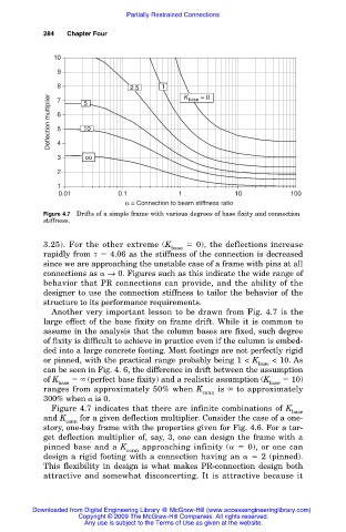
Figure 4.7 Drifts of a simple frame with various degrees of base fixity and connection
stiffness.
3.25). For the other extreme (K 0), the deflections increase
base
rapidly from 4.06 as the stiffness of the connection is decreased
since we are approaching the unstable case of a frame with pins at all
connections as → 0. Figures such as this indicate the wide range of
behavior that PR connections can provide, and the ability of the
designer to use the connection stiffness to tailor the behavior of the
structure to its performance requirements.
Another very important lesson to be drawn from Fig. 4.7 is the
large effect of the base fixity on frame drift. While it is common to
assume in the analysis that the column bases are fixed, such degree
of fixity is difficult to achieve in practice even if the column is embed-
ded into a large concrete footing. Most footings are not perfectly rigid
or pinned, with the practical range probably being 1 < K < 10. As
base
can be seen in Fig. 4. 6, the difference in drift between the assumption
of K (perfect base fixity) and a realistic assumption (K 10)
base base
ranges from approximately 50% when K is to approximately
conn
300% when is 0.
Figure 4.7 indicates that there are infinite combinations of K
base
and K for a given deflection multiplier. Consider the case of a one-
conn
story, one-bay frame with the properties given for Fig. 4.6. For a tar-
get deflection multiplier of, say, 3, one can design the frame with a
pinned base and a K approaching infinity ( 0), or one can
conn
design a rigid footing with a connection having an 2 (pinned).
This flexibility in design is what makes PR-connection design both
attractive and somewhat disconcerting. It is attractive because it
Downloaded from Digital Engineering Library @ McGraw-Hill (www.accessengineeringlibrary.com)
Copyright © 2009 The McGraw-Hill Companies. All rights reserved.
Any use is subject to the Terms of Use as given at the website.