
Page 302 - Handbook of Structural Steel Connection Design and Details
P. 302
Partially Restrained Connections
Partially Restrained Connections 287
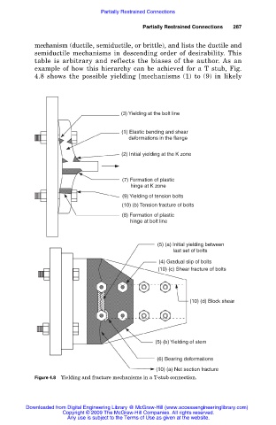
mechanism (ductile, semiductile, or brittle), and lists the ductile and
semiductile mechanisms in descending order of desirability. This
table is arbitrary and reflects the biases of the author. As an
example of how this hierarchy can be achieved for a T stub, Fig.
4.8 shows the possible yielding [mechanisms (1) to (9) in likely
(3) Yielding at the bolt line
(1) Elastic bending and shear
deformations in the flange
(2) Initial yielding at the K zone
(7) Formation of plastic
hinge at K zone
(9) Yielding of tension bolts
(10) (b) Tension fracture of bolts
(8) Formation of plastic
hinge at bolt line
(5) (a) Initial yielding between
last set of bolts
(4) Gradual slip of bolts
(10) (c) Shear fracture of bolts
(10) (d) Block shear
(5) (b) Yielding of stem
(6) Bearing deformations
(10) (a) Net section fracture
Figure 4.8 Yielding and fracture mechanisms in a T-stub connection.
Downloaded from Digital Engineering Library @ McGraw-Hill (www.accessengineeringlibrary.com)
Copyright © 2009 The McGraw-Hill Companies. All rights reserved.
Any use is subject to the Terms of Use as given at the website.