
Page 104 - Hardware Implementation of Finite-Field Arithmetic
P. 104
mod m Operations 87
end if;
end process register_ty;
shift_register: process(clk)
begin
if clk’event and clk = ‘1’ then
if load = ‘1’ then int_x <= x;
elsif update = ‘1’ then int_x <=
‘0’&int_x(K-1 downto 1);
end if;
end if;
end process shift_register;
xi <= int_x(0);
The complete model additionally includes a k-state counter and a
control unit.
3.6 FPGA Implementations
Several multipliers have been implemented within Spartan3 (speed -5)
programmable devices. As before, the times (period, Total Time) are
expressed in ns, and the parameters FFs and LUTs represent the
numbers of flip-flops and look-up tables, respectively. Every slice
includes two flip-flops and two look-up tables. All the source files are
available at www.arithmetic-circuits.org.
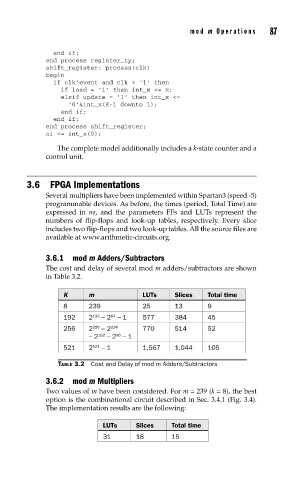
3.6.1 mod m Adders/Subtractors
The cost and delay of several mod m adders/subtractors are shown
in Table 3.2.
K m LUTs Slices Total time
8 239 25 13 9
64
192 2 192 – 2 − 1 577 384 45
256 2 256 – 2 224 770 514 52
96
– 2 192 – 2 − 1
521 2 521 – 1 1,567 1,044 105
TABLE 3.2 Cost and Delay of mod m Adders/Subtractors
3.6.2 mod m Multipliers
Two values of m have been considered. For m = 239 (k = 8), the best
option is the combinational circuit described in Sec. 3.4.1 (Fig. 3.4).
The implementation results are the following:
LUTs Slices Total time
31 18 15