
Page 55 - Hardware Implementation of Finite-Field Arithmetic
P. 55
38 Cha pte r T w o
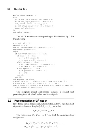
entity tpkma_reducer is
port (
x: in std_logic_vector (N-1 downto 0);
m: in std_logic_vector(K-1 downto 0);
clk, reset, start: in std_logic;
z: out std_logic_vector (K-1 downto 0);
done: out std_logic
);
end tpkma_reducer;
The VHDL architecture corresponding to the circuit of Fig. 2.5 is
the following:
a <= not (m) + ‘1’;
product <= q*a;
sum <= (zero&product(K-1 downto 0)) + r;
registers: process(clk)
begin
if clk’event and clk = ‘1’ then
if load = ‘1’ then
q <= x(N-1 downto K);
r <= zero & x(K-1 downto 0);
elsif reload=‘1’ then
q <= (long_zero & r(T-1 downto k));
r <= zero & r(K-1 downto 0);
elsif update = ‘1’ then
q <= product(N-1 downto k);
r <= sum;
end if;
end if;
end process registers;
q_equal_zero <= ‘1’ when q = very_long_zero else ‘0’;
r_minus_m <= (‘0’&r(K-1 downto 0)) + (‘1’&a);
with r_minus_m(k) select z <= r_minus_m(K-1 downto 0) when ‘0’,
r(K-1 downto 0) when others;
The complete model additionally includes a control unit
generating the load, reload, update, and done signals.
2.3 Precomputation of 2 mod m
ik
First define a mixed-radix numeration system [DBS06] based on a set
of positive bit-vector lengths l , l , l , . . . , l such that
0 1 2 s − 1
l + l + l + . . . + l = n
0 1 2 s − 1
l
l
l
The radices are 2 0 , 2 1 , . . . , 2 s−1 , so that the corresponding
weights are
W = 1, W = 2 0 , W = 2 1 . 2 0 l = 2 1 l + 0 l , . . . ,
l
l
0 1 2
W = 2 l s−2 . ... . 2 1 . 2 = 2 l s−2 + ... l + + l 0
1 .
l
l 0
s − 1