
Page 120 - High Power Laser Handbook
P. 120
90 G a s , C h e m i c a l , a n d F r e e - E l e c t r o n L a s e r s High-Power Fr ee-Electr on Lasers 91
linac-operating frequency to a very high accuracy. It is not unusual to
require a 10-m optical cavity length to be correct to within a micrometer.
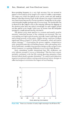
The range over which the optical cavity can be varied and still result in
lasing is called the detuning length. In the infrared, the output’s bandwidth
may seem broad because it is Fourier transform–limited due to the subpi-
cosecond pulse lengths (perhaps only 10 waves long). The bandwidth that
is observed in the output is due to the interplay between the slippage of
the electron pulse back one optical wavelength for each wiggler period
and the optical cavity length, which may be shorter than the interpulse
spacing by a small amount (see Fig. 4.6a and b).
The optical cavity must operate in a vacuum and usually must be
remotely controlled because of the radiation environment. The low
outcoupling and tight optical modes typically found yield high peak
and average powers on the optics. Higher-energy machines produce
significant fluxes of hard UV at the FEL harmonics, which can lead to
mirror damage. 25–27 Outcoupling the power requires a transmissive
optic (potential materials and heating issues), hole outcoupling (rela-
tively inefficient), unstable ring resonator designs with a scraper (extra
mirror bounces), or a grating (difficulty in survival at high fluence).
Early simulation studies determined that FEL oscillators can
6
only tolerate around 0.2 waves of distortion. This has been experi-
mentally confirmed, with the FEL output showing saturation when
thermal effects lead to greater distortion. To control such distortion
28
requires exceptional mirror coatings and advanced mirror designs or
other techniques to minimize the impact of local heating.
12
10 8
Power (arb. units) 6 4
2
0
−25 −20 −15 −10 −5 0 5
Cavity detuning (micrometers)
Figure 4.6a Power as a function of cavity length detuning in the IR Demo FEL.