
Page 122 - High Power Laser Handbook
P. 122
92 G a s , C h e m i c a l , a n d F r e e - E l e c t r o n L a s e r s High-Power Fr ee-Electr on Lasers 93
that could activate the environs. This third benefit is a very substantial
factor in maintenance and radiation shielding. The price one pays for
such benefits is the addition of a small amount of magnetic beam trans-
port and the forced elimination of instabilities, which can result from
feedback of the beam on itself. These issues have largely been resolved
for optimized designs of low-frequency cavities. 29
Optimization and control of the high-current transport to permit
lasing and energy recovery are worthy of a significant paper on their
own, and the scope is beyond what can be treated here. At high
charge, there are issues associated with maintaining the electron
beam quality as one accelerates, and especially as one bends, the
beam. Some areas of this physics are still under active investigation
and remain unresolved in terms of accurate quantitative predictability.
The general strategy, though, is to allow the beam bunches to remain
temporally long until just before the FEL interaction, so as to minimize
external and self-interactions.
In addition, the electron beam’s energy spread is large after the FEL
interaction, and magnetic transport is highly chromatic. No beam can
be lost during the transport, because even a few microamperes of cur-
rent deposited locally in a vacuum pipe wall can burn a hole through
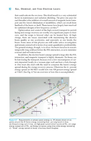
it. One must also deal with the need to compress the beam’s energy
spread during the energy-recovery process. Otherwise the 6+ percent
energy spread at 100 MeV would turn into 100 percent energy spread
at 5 MeV. (See Fig. 4.7 for an overview of how this is accomplished.)
E
(a)
φ
E
φ
E (e)
E
(b) E φ
φ
(d)
φ
E (c)
φ
(f)
Figure 4.7 Requirements on phase space (energy vs. RF phase) shown at six
points around the IR Demo energy recovering linac. (a) Long bunch in linac.
(b) Chirped energy out of linac. (c) High-peak current (short bunch) at FEL. (d) Large
energy spread out of FEL. (e) Energy compress using chirp while energy recovering.
(f ) “Small” energy spread at dump. (Courtesy David Douglas)