
Page 221 - High Power Laser Handbook
P. 221
190 So l i d - S t at e La s e r s Zigzag Slab Lasers 191
Combining Eqs. (8.2), (8.3), and (8.4), we find that for a rod at con-
stant heat loading, the focal length of the thermal lens is independent
of the rod diameter:
dn
k
f = 2/ LQ (8.5)
dT
As a result, thermal lensing is the main limitation to power scaling in
rod-based devices.
In slabs, however, zigzag propagation between the two cooled
surfaces averages over the temperature gradients and results in virtu-
ally no thermal lensing to the first order. Thus, the main limitation in
early side-pumped slabs was thermally induced stress, which can
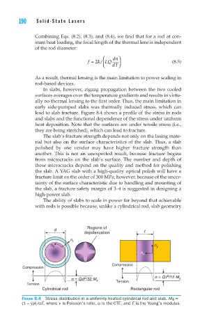
lead to slab fracture. Figure 8.4 shows a profile of the stress in rods
and slabs and the functional dependence of the stress under uniform
heat deposition. Note that the surfaces are under tensile stress (i.e.,
they are being stretched), which can lead to fracture.
The slab’s fracture strength depends not only on the lasing mate-
rial but also on the surface characteristics of the slab. Thus, a slab
polished by one vendor may have higher fracture strength than
another. This is not an unexpected result, because fracture begins
from microcracks on the slab’s surface. The number and depth of
these microcracks depend on the quality and method for polishing
the slab. A YAG slab with a high-quality optical polish will have a
fracture limit on the order of 300 MPa; however, because of the uncer-
tainty of the surface characteristic due to handling and mounting of
the slab, a fracture safety margin of 3–4 is suggested in designing a
high-power slab.
The ability of slabs to scale in power far beyond that achievable
with rods is possible because, unlike a cylindrical rod, slab geometry
d Regions of t
depolarization
n
d r
n θ n y
n x
Compression
Compression
σ = Qt /12 M
2
2
σ = Qd /32 M s s
Tension Tension
Cylindrical rod Rectangular rod
Figure 8.4 Stress distribution in a uniformly heated cylindrical rod and slab. Ms =
(1 – ν)k/αE, where ν is Poisson’s ratio, α is the CTE, and E is the Young’s modulus.