
Page 224 - High Power Laser Handbook
P. 224
192 So l i d - S t at e La s e r s Zigzag Slab Lasers 193
coolant is typically confined by a pair of windows that are sealed
against the slab’s TIR faces. This slab architecture has several
design issues that have been addressed over the years using vari-
ous techniques.
Non-Zigzag Axis Temperature Nonuniformity
The slab coolant is usually sealed using an O-ring or gasket that is
positioned near the slab edges. This technique usually results in a
cold region of unpumped material at the top and bottom edges of the
slab, leading to OPD and wavefront distortion. To address this prob-
lem, scientists at Lawrence Livermore National Laboratory (LLNL) in
the early 1980s introduced the concept of edge bars. Edge bars are
typically metallic bars attached to the edges of the slab; depending on
the need, these bars can cool the edges using coolant flow or heat the
edges via embedded resistive-heating elements. This allows the user
to control the slab’s edge temperature and reduce or eliminate the
OPD near the slab’s edges (Fig. 8.6a).
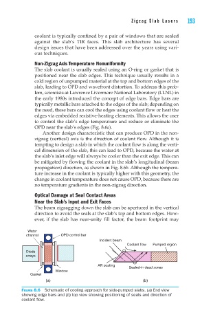
Another design characteristic that can produce OPD in the non-
zigzag (vertical) axis is the direction of coolant flow. Although it is
tempting to design a slab in which the coolant flow is along the verti-
cal dimension of the slab, this can lead to OPD, because the water at
the slab’s inlet edge will always be cooler than the exit edge. This can
be mitigated by flowing the coolant in the slab’s longitudinal (beam
propagation) direction, as shown in Fig. 8.6b. Although the tempera-
ture increase in the coolant is typically higher with this geometry, the
change in coolant temperature does not cause OPD, because there are
no temperature gradients in the non-zigzag direction.
Optical Damage at Seal Contact Areas
Near the Slab’s Input and Exit Faces
The beam zigzagging down the slab can be apertured in the vertical
direction to avoid the seals at the slab’s top and bottom edges. How-
ever, if the slab has near-unity fill factor, the beam footprint may
Water
channel OPD control bar
Incident beam
Coolant flow Pumped region
Diode
arrays
AR coating
Sealed-in dead zones
Window
Gasket
(a) (b)
Figure 8.6 Schematic of cooling approach for side-pumped slabs. (a) End view
showing edge bars and (b) top view showing positioning of seals and direction of
coolant flow.