
Page 279 - High Power Laser Handbook
P. 279
248 So l i d - S t at e La s e r s Thin-Disc Lasers 249
35
30
25
Heat load (kW) 20
15
Heat load inside disk
Transmission through HR
10
5
0
0 200 400 600 800 1000
Time (µs)
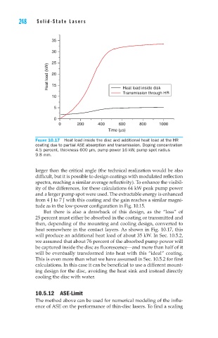
Figure 10.17 Heat load inside the disc and additional heat load at the HR
coating due to partial ASE absorption and transmission. Doping concentration
4.5 percent, thickness 600 µm, pump power 16 kW, pump spot radius
9.8 mm.
larger than the critical angle (the technical realization would be also
difficult, but it is possible to design coatings with modulated reflection
spectra, reaching a similar average reflectivity). To enhance the visibil-
ity of the differences, for these calculations 64 kW peak pump power
and a larger pump spot were used. The extractable energy is enhanced
from 4 J to 7 J with this coating and the gain reaches a similar magni-
tude as in the low-power configuration in Fig. 10.15.
But there is also a drawback of this design, as the “loss” of
25 percent must either be absorbed in the coating or transmitted and
then, depending of the mounting and cooling design, converted to
heat somewhere in the contact layers. As shown in Fig. 10.17, this
will produce an additional heat load of about 35 kW. In Sec. 10.5.2,
we assumed that about 76 percent of the absorbed pump power will
be captured inside the disc as fluorescence—and more than half of it
will be eventually transformed into heat with this “ideal” coating.
This is even more than what we have assumed in Sec. 10.5.2 for first
calculations. In this case it can be beneficial to use a different mount-
ing design for the disc, avoiding the heat sink and instead directly
cooling the disc with water.
10.5.12 ASE-Limit
The method above can be used for numerical modeling of the influ-
ence of ASE on the performance of thin-disc lasers. To find a scaling