
Page 325 - High Power Laser Handbook
P. 325
294 So l i d - S t at e La s e r s Heat-Capacity Lasers 295
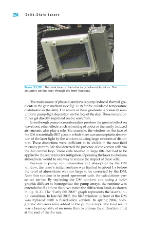
Figure 11.30 The front face of the intracavity deformable mirror. The
actuators can be seen through the front faceplate.
The main source of phase distortions is pump-induced thermal gra-
dients in the gain medium (see Fig. 11.18 for the calculated temperature
distribution in the slab). The source of these gradients is primarily non-
uniform pump-light deposition on the face of the slab. These nonunifor-
mities get directly imprinted on the wavefront.
Even though pump nonuniformities produce the greatest effect on
wavefront, other effects, such as heating of optics or thermally induced
air currents, also play a role. For example, the window on the face of
the DM was initially BK7 glass in which there was unacceptable absorp-
tion of the laser light by the window, causing large amounts of distor-
tion. These distortions were sufficient to be visible in the near-field
intensity pattern. We also detected the presence of convection cells via
the AO control loop. These cells resulted in large tilts that had to be
applied to the rear mirror for mitigation. Operating the laser in a helium
atmosphere would be one way to reduce the impact of these cells.
Because of pump nonuniformities and absorption by the DM
window, the laser’s initial runtime was limited to about 1 s before
the level of aberrations was too large to be corrected by the DM.
Note this runtime is in good agreement with the calculations pre-
sented earlier. By replacing the DM window and using a holo-
graphic diffuser to homogenize the pump arrays, the runtime was
extended to 5 s at less than two times the diffraction limit, as shown
in Fig. 11.31. The “Early fall 2005” graph represents the laser’s ini-
tial condition. In late fall 2005, the BK7 window in front of the DM
was replaced with a fused-silica version. In spring 2006, holo-
graphic diffusers were added to the pump arrays. The final result
was a beam quality of no more than two times the diffraction limit
at the end of the 5-s run.