
Page 324 - High Power Laser Handbook
P. 324
292 So l i d - S t at e La s e r s Heat-Capacity Lasers 293
(a) (b)
Figure 11.28 Current configuration of the heat-capacity laser at Lawrence
Livermore National Laboratory. (a) End view and (b) side view.
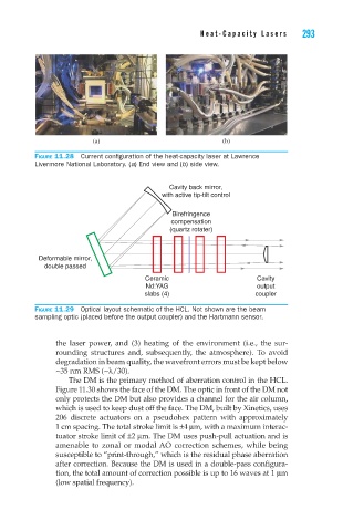
Cavity back mirror,
with active tip-tilt control
Birefringence
compensation
(quartz rotater)
Deformable mirror,
double passed
Ceramic Cavity
Nd:YAG output
slabs (4) coupler
Figure 11.29 Optical layout schematic of the HCL. Not shown are the beam
sampling optic (placed before the output coupler) and the Hartmann sensor.
the laser power, and (3) heating of the environment (i.e., the sur-
rounding structures and, subsequently, the atmosphere). To avoid
degradation in beam quality, the wavefront errors must be kept below
~35 nm RMS (~l/30).
The DM is the primary method of aberration control in the HCL.
Figure 11.30 shows the face of the DM. The optic in front of the DM not
only protects the DM but also provides a channel for the air column,
which is used to keep dust off the face. The DM, built by Xinetics, uses
206 discrete actuators on a pseudohex pattern with approximately
1 cm spacing. The total stroke limit is ±4 mm, with a maximum interac-
tuator stroke limit of ±2 mm. The DM uses push-pull actuation and is
amenable to zonal or modal AO correction schemes, while being
susceptible to “print-through,” which is the residual phase aberration
after correction. Because the DM is used in a double-pass configura-
tion, the total amount of correction possible is up to 16 waves at 1 mm
(low spatial frequency).