
Page 22 - High Temperature Solid Oxide Fuel Cells Fundamentals, Design and Applications
P. 22
Introduction to SOFCs 3
The zirconia lighting filament was not successful in competing with tungsten
lamps and Nernst's invention languished until the late 1930s when a fuel cell
concept based on zirconium oxide was demonstrated at the laboratory scale by
Baur and Preis [SI. They used a tubular crucible made from zirconia stabilised
with 15 wt% yttria as the electrolyte. Iron or carbon was used as the anode and
magnetite (Fe304) as the cathode. Hydrogen or carbon monoxide was the fuel on
the inside of the tube and air was the oxidant on the outside. Eight cells were
connected in series to make the first SOFC stack. They obtained power from the
device and speculated that this solid oxide fuel cell could compete with batteries.
But several improvements were necessary before this would be possible. For
example, the electrolyte manufacturing process was too crude and needed
optimising, especially to make the electrolyte thinner to reduce the cell
resistance from around 2 Q. In addition, the electrodes were inadequate,
especially the cathode Fe304 which readily oxidised. Also, the power density was
small with the stacking arrangement used, the connections between many cells
had to be developed, and the understanding of fuel reactions and system
operation needed much attention.
It was not until the 19 50s that experiments began on pressed or tape-cast discs
of stabilised zirconia when a straightforward design of test system was developed
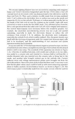
which is still in use today. The essentials of the apparatus are shown in Figure
1.2a. A flat disc of stabilised zirconia, with anode and cathode on its two sides,
was sealed to a ceramic tube and inserted in a furnace held at red heat [6]. A
smaller diameter tube was inserted into the ceramic tube to bring fuel to the
anode, and another tube brought oxidant gas to the cathode side. Current
collector wires and voltage measurement probes were brought out from the
electrode surfaces. Once a flat plate of electrolyte had been used, it was easy to see
how the flat plate voltaic stack could be built up with interconnecting separator
plates to build a realistic electrochemical reactor, as shown in Figure 1.2b. The
interconnect plate is essentially made from the anode current collector and the
Zirconia + electrodes Furnace
r'
Fuel Oxidant
4
Interconnects V
Anode Cathode leads
a b
Figure 1.2 (a) Flatplate test cell; (b)planarstackofcellsandinterconnects.