
Page 281 - How To Implement Lean Manufacturing
P. 281
258 Cha pte r S i x tee n
Stators were prepared by welding and grinding, and then were placed at the front
of four coil insertion cells. The insertion cells had a build schedule and the supervisor
hung markers so the stator prep station knew which stator was required. Three models
of stators were available: one large model and two smaller ones. Wire was coiled by the
coiling machines in a “coiling island” and then mounted on rolling coil trees for trans-
port to the coil insertion cells. The line operators would leave the cell and go get the
wire they needed. Forty trees were queued up at the “coiling island.” The trees were
color-coded for different coil arrangements required on different motors. Four coil
insertion cells were available, each staffed with four operators. All four cells were capa-
ble of making all ten models.
From insertion, the wound stators went to lacing and press where a pool of nine
operators would complete these tasks. The work load varied at this station, due to model
mix, so these operators were also used to transport motors in the production line. From
lace and press the motors were transported to Hipot, an electrical stress test.
After Hipot, the stators accumulated to form a batch prior to going to the preheat
oven. Due to oven size, maximum batches would be 12 to 24 motors, depending upon
the large/small ratio. After preheat, they were moved to a batch varnish operation,
which varied in batch size from 6 to 12, and after varnish, the motors were moved to the
curing oven where batches of 24 to 48 were cured.
Following the cure, stators were first polished and then moved to the CNC lathe
were they were trimmed and sent to final assembly, which consisted of two final assem-
bly cells, operating in parallel. Each cell was staffed by two operators. Following this,
the motors underwent a series of tests, including visual inspection, and then were
passed on to packing.
Some comments on the planning. There was a three month forecast and a monthly
plan, both of which were largely ignored at production. A weekly update would come
from Minneapolis on Friday, for the following week’s production. The planning staff
turned this update into a daily production plan and sent it to shipping along with a
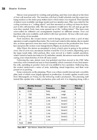
Monthly Demand Pick up Stator Wire Coil
Model (Avg.) Frequency Size Pattern
Ia 1130 Daily Large A
Ib 720 Daily Large B
II 950 3/wk, M,W, F Small-1 C
III 475 1/wk Small-2 D
IV 175 1/wk Small-2 D
V 90 1/wk Small-2 D
VI 50 1/wk Small-2 D
VII 20 1/wk Small-2 E
VIII 20 1/wk Small-2 E
IX 10 1/wk Small-2 E
Total 3550
TABLE 16-7 QED Motors, Model Mix Demand