
Page 170 - Human Inspired Dexterity in Robotic Manipulation
P. 170
168 Human Inspired Dexterity in Robotic Manipulation
q a5
q a3
q a4
q 31
q 32
q 12
q 33
q 13 q 22
y q 21
q 34 q 11
q 14
q 23
q 15
x 03
q 24
q a2
x x 02
O x 01
z
q a1
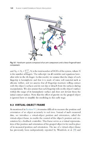
Fig. 9.1 Hand-arm system composed of an arm component and a three-fingered hand
component.
and N D ¼ N a + P N N i is the total number of DOFs of the system, where N
i¼1
is the number of fingers. The subscript i in all variables and equations here-
after refer to the ith finger. In this model, we assume that the shape of each
fingertip is hemispheric and that it is made of some soft material such as
silicone rubber, and we assume that all fingertips maintain rolling contact
with the object’s surfaces and do not slip or detach from the surfaces during
manipulation. We also assume that each fingertip rolls on the object’s surface
within the range of its hemispheric surface and does not deviate from the
initial contact surface. Note that the effect of gravity on the grasped object
is ignored here to simplify the modeling in this early stage.
9.3 VIRTUAL-OBJECT FRAME
As mentioned in Section 9.1, it remains difficult to measure the position and
orientation of an object accurately in real time. Instead of such measured
data, we introduce a virtual-object position and orientation, called the
virtual-object frame, to enable the control of the object’s position and ori-
entation by a feedback controller. This frame serves as a virtual representa-
tion of the position and orientation of the grasped object to be used in place
of its measured position and orientation. The use of a virtual-object frame
has previously been independently reported by Wimb€ock et al. [9] and