
Page 173 - Human Inspired Dexterity in Robotic Manipulation
P. 173
A Grasping and Manipulation Scheme 171
because the time delay does not affect the current value of the virtual-object
frame. In this method, the time delay due to the sampling rate is considered
independently of the time delay induced by the computational cost of image
processing and the latency of data communication. This is because these phe-
nomena and their countermeasures are qualitatively different. The length of
the time delay due to the sampling rate varies with the timing of when the last
instantaneous visual image was captured. For example, the time delay varies
from 0 to 33 ms when a 30 Hz NTSC camera is used. This varying time delay
is denoted by t sample , and it satisfies the following inequality:
1
0 t sample < , (9.5)
h
where h denotes the sampling rate.
The other time delay, caused by the computational cost of image proces-
sing and data communication latency, is denoted by t image , and the total time
delay is denoted by t delay and is expressed as follows:
t delay ¼ t sample + t image : (9.6)
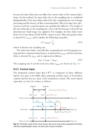
The sampling rate h and the total time delay t delay are shown in Fig. 9.3.
9.4.2 Control Input
The proposed control input uðtÞ2 N D is composed of three different
inputs: one, u s (t), is for stable-object grasping; another, u p (t), is for position
control; and the last one, u o (t), is for orientation control. The total control
input u(t) can then be written as follows:
Capture Capture
((t1+tsample)-tdelay=t1-timage)
1/h
x(t0-timage) x(t1-timage)=x(t-tdelay)
Vision sensor Time (s)
timage timage tsample
xd vir (t0) xd vir (t1)
Present
Controller Time (s)
xd vir (t1+tsample)=xd vir (t)
xvir(t0-timage) xvir(t1-timage)=xvir(t-tdelay)
Joint encoder Time (s)
Fig. 9.3 Time-line chart of the visual sensor, the servo loop of the proposed controller,
and the proprioceptive sensor on each joint (rotary encoder).