Page 178 - Human Inspired Dexterity in Robotic Manipulation
P. 178

176   Human Inspired Dexterity in Robotic Manipulation


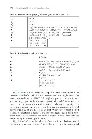
          Table 9.2 Nominal desired grasping force and gains for the simulations
                            10.0 N
            f d
                            4.762
           K p
                            0.238
           K o
                            diag 1:003,0:651,0:735,0:278,0:177Þ 10  1  (Ns m/rad)
                               ð
           C a
                            diag 0:606,0:687,0:786,0:642,0:198Þ 10  2  (Ns m/rad)
                               ð
           C 1
                            diag 0:468,0:780,0:318,0:099Þ 10  2  (Ns m/rad)
                               ð
           C 2
                            diag 0:648,0:780,0:318,0:099Þ 10  2  (Ns m/rad)
                               ð
           C 3
                                            T
           x d              ð 0:100,0:500,0:700Þ (m)
                           2                 3
                             0:88  0:32  0:34
           R d
                             0:34 0:94   0:00
                           4                 5
                             0:32  0:12 0:94
          Table 9.3 Initial conditions of the simulations
                                      0 (rad/s)
           _ q
                                                                     T
           q a                        ð  0:183,  1:369,1:898,1:343,  0:787Þ (rad)
                                                                  T
          q 01                        ð 1:007,0:235,  0:771,1:338,0:328Þ (rad)
                                                             T
          q 02                        ð 0:242,  0:733,1:122,0:754Þ (rad)
                                                             T
          q 03                        ð 2:019,  0:924,0:912,1:088Þ (rad)
                                      0 (m/s)
           _ x
                                                      T
           x                          ð 0:158,0:501,0:681Þ (m)
           ω                          0 (rad/s)
                                     2              3
                                       1:00 0:00 0:00
           R
                                     4 0:00 1:00 0:00  5
                                       0:00 0:00 1:00
             Figs. 9.4 and 9.5 show the transient responses of the x component of the
          measured x and of θ z , which is the measured rotational angle around the
          z-axis expressed in terms of XYZ Euler angles, respectively. In these figures,
                       represent the transient responses of x and θ z when the pro-
          x new and θ z new
                                                                       rep-
          posed control inputs u p (t) and u o (t) are utilized, whereas x pre and θ z pre
          resent the transient responses of x and θ z when the previously proposed
                                     (t) are utilized. When the proposed method
                           (t) and u o real
          control inputs u p real
          is used, the oscillation is reduced, and the convergence rate is faster com-
          pared with the case in which the previous method is used, even with the
          low-sampling rate and long-time delays.
             Figs. 9.6 and 9.7 show the behavior of the positions and orientations of
          the measured- and virtual-object frames when the control inputs u p tðÞ and
   173   174   175   176   177   178   179   180   181   182   183