
Page 183 - Human Inspired Dexterity in Robotic Manipulation
P. 183
A Grasping and Manipulation Scheme 181
Table 9.6 Nominal desired grasping force and gains
1.1 N
f d
70.0
K p
4.0 10 2
K o
diag 0:07,0:07,0:05,0:03Þ 10 2 (Ns m/rad)
ð
C 1
diag 0:07,0:07,0:05,0:03Þ 10 2 (Ns m/rad)
ð
C 2
diag 0:07,0:07,0:05,0:03Þ 10 2 (Ns m/rad)
ð
C 3
Triple-fingered robotic hand
Micron tracker
Marker
Object
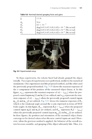
Fig. 9.9 Experimental setup.
In these experiments, the robotic hand had already grasped the object
initially. Two types of experiments were performed, similar to the numerical
simulations. One experiment used the proposed method, and the other used
the previously proposed method. Fig. 9.10 shows the transient responses of
the x component of the position of the measured-object frame, x. In this
figure, x new represents the transient response of x(t t delay ) when the pro-
posed control inputs u p tðÞ and u o tðÞ are utilized, and x pre represents the tran-
sient response of x(t t delay ) when the previously proposed control inputs
(t) are utilized. Fig. 9.11 shows the transient responses of θ x ,
u p real (t) and u o real
which is the rotational angle around the x-axis expressed in terms of XYZ
represents θ x (t t delay ) when the proposed
Euler angles. In this figure, θ x new
represents θ x (t t delay )
control inputs u p (t) and u o (t) are utilized, and θ x pre
(t) are utilized.
when the previously proposed control inputs u p real (t) and u o real
In these figures, the position and orientation of the measured-object frame
converge to the desired values when the new control inputs are used. How-
ever, when the previous method is applied, the behavior of the overall sys-
tem becomes unstable, and grasping of the object ultimately fails. Thus, it is