
Page 201 - Hybrid-Renewable Energy Systems in Microgrids
P. 201
Sensitivity and transient stability analysis of fixed speed wind generator 181
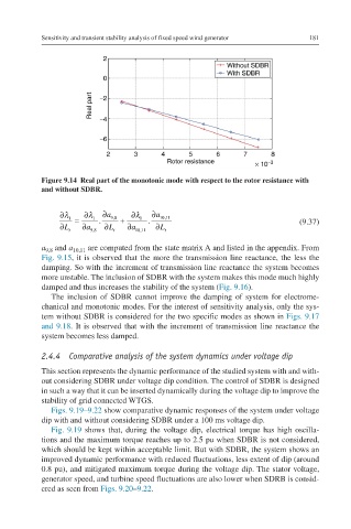
Figure 9.14 Real part of the monotonic mode with respect to the rotor resistance with
and without SDBR.
∂ λ 1 = ∂ λ 1 . ∂a 9,8 + ∂ λ 1 . ∂a 10,11
1
1
∂L ∂a ∂L ∂a ∂L (9.37) ∂λ ∂Lt=∂λ ∂a9,8.∂a9,8∂Lt+∂
t 9,8 t 10,11 t λ ∂a10,11.∂a10,11∂Lt
1
a and a 10,11 are computed from the state matrix A and listed in the appendix. From
9,8
Fig. 9.15, it is observed that the more the transmission line reactance, the less the
damping. So with the increment of transmission line reactance the system becomes
more unstable. The inclusion of SDBR with the system makes this mode much highly
damped and thus increases the stability of the system (Fig. 9.16).
The inclusion of SDBR cannot improve the damping of system for electrome-
chanical and monotonic modes. For the interest of sensitivity analysis, only the sys-
tem without SDBR is considered for the two specific modes as shown in Figs. 9.17
and 9.18. It is observed that with the increment of transmission line reactance the
system becomes less damped.
2.4.4 Comparative analysis of the system dynamics under voltage dip
This section represents the dynamic performance of the studied system with and with-
out considering SDBR under voltage dip condition. The control of SDBR is designed
in such a way that it can be inserted dynamically during the voltage dip to improve the
stability of grid connected WTGS.
Figs. 9.19–9.22 show comparative dynamic responses of the system under voltage
dip with and without considering SDBR under a 100 ms voltage dip.
Fig. 9.19 shows that, during the voltage dip, electrical torque has high oscilla-
tions and the maximum torque reaches up to 2.5 pu when SDBR is not considered,
which should be kept within acceptable limit. But with SDBR, the system shows an
improved dynamic performance with reduced fluctuations, less extent of dip (around
0.8 pu), and mitigated maximum torque during the voltage dip. The stator voltage,
generator speed, and turbine speed fluctuations are also lower when SDRB is consid-
ered as seen from Figs. 9.20–9.22.