
Page 282 - Hydrocarbon
P. 282
Surface Facilities 269
process design should reflect this. However, early models of the process along with
broad cost estimates are needed to progress, and both design detail and cost ranges
narrow as projects develop through the feasibility study and field development
planning phases (see Chapter 12 for a description of project phases).
11.1.1.4. Process flow schemes
To give some structure to the process design it is common to present information and
ideas in the form of process flow schemes (PFS). These can take a number of forms and
be prepared in various levels of detail. A typical approach is to divide the process into
a hierarchy, differentiating the main process from both utility and safety processes.
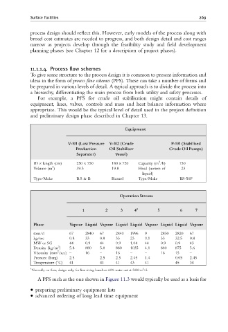
For example, a PFS for crude oil stabilisation might contain details of
equipment, lines, valves, controls and mass and heat balance information where
appropriate. This would be the typical level of detail used in the project definition
and preliminary design phase described in Chapter 13.
Equipment
V-101 (Low Pressure V-102 (Crude P-101 (Stabilised
Production Oil Stabiliser Crude Oil Pumps)
Separator) Vessel)
3
ID length (cm) 250 750 180 720 Capacity (m /h) 150
3
Volume (m ) 39.5 19.8 Head (metres of 23
liquid)
Type/Make B.S & B Kunzel Type/Make BS-50F
Operation Stream
1 2 3 4 a 5 6 7
Phase Vapour Liquid Vapour Liquid Liquid Vapour Liquid Liquid Vapour
tons/d 67 2840 67 2840 1996 9 2830 2820 67
kg/sec 0.8 33 0.8 33 23 0.1 33 32.5 0.8
MW or SG 44 0.9 44 0.9 1.04 44 0.9 0.9 43
3
Density (kg/m ) 5.8 880 5.8 880 1035 4.1 880 875 5.6
2
Viscosity (mm /sec) – 16 – 16 – – 16 15 –
Pressure (barg) 2.5 2.5 2.5 2.45 1.4 0.05 2.45
Temperature (1C) 41 41 41 43 41 45 34
a 3
Normally no flow, design only, for line sizing based on 60% water cut at 3000 m /d.
A PFS such as the one shown in Figure 11.3 would typically be used as a basis for
preparing preliminary equipment lists
advanced ordering of long lead time equipment