
Page 246 - Hydrocarbon Exploration and Production Second Edition
P. 246
Well Dynamic Behaviour 233
damaged zone
convergence
P e P
Pressure drop e
due to
radial inflow
Pressure drop
P wf due to skin P wf
radial inflow
Damage skin Geometric skin
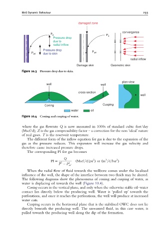
Figure 10.3 Pressure drop due to skin.
plan-view
well well
cross-section
well
Coning Cusping
water oil
Figure 10.4 Coning and cusping of water.
where the gas flowrate Q is now measured in 1000s of standard cubic feet/day
(Mscf/d); Z is the gas compressibility factor – a correction for the non ‘ideal’ nature
of real gases. T is the reservoir temperature.
The different form of the inflow equation for gas is due to the expansion of the
gas as the pressure reduces. This expansion will increase the gas velocity and
therefore cause increased pressure drops.
The corresponding PI for gas becomes
Q 2 3 2
PI ¼ ðMscf =d=psi Þ or ðm =d=bar Þ
2
¯ P P 2
wf
When the radial flow of fluid towards the wellbore comes under the localised
influence of the well, the shape of the interface between two fluids may be altered.
The following diagrams show the phenomena of coning and cusping of water, as
water is displacing oil towards the well (Figure 10.4).
Coning occurs in the vertical plane, and only when the otherwise stable oil–water
contact lies directly below the producing well. Water is ‘pulled up’ towards the
perforations, and once it reaches the perforations, the well will produce at increased
water cuts.
Cusping occurs in the horizontal plane that is the stabilised OWC does not lie
directly beneath the producing well. The unwanted fluid, in this case water, is
pulled towards the producing well along the dip of the formation.