
Page 44 - Hydrocarbon Exploration and Production Second Edition
P. 44
Exploration 31
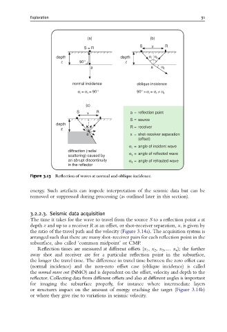
(a) (b)
S x R
S = R
depth depth α i α r
z 90° z
a a α t
normal incidence oblique incidence
α = α = 90° 90° >α = α ≠ α t
r
i
i
r
(c)
S x R a = reflection point
S = source
depth
z R = receiver
a x = shot-receiver separation
(offset)
α = angle of incident wave
i
diffraction (radial α
scattering) caused by r = angle of reflected wave
an abrupt discontinuity α = angle of refracted wave
t
in the reflector
Figure 3.13 Re£ection of waves at normal and oblique incidence.
energy. Such artefacts can impede interpretation of the seismic data but can be
removed or suppressed during processing (as outlined later in this section).
3.2.2.3. Seismic data acquisition
The time it takes for the wave to travel from the source S to a reflection point a at
depth z and up to a receiver R at an offset, or shot-receiver separation, x, is given by
the ratio of the travel path and the velocity (Figure 3.14a). The acquisition system is
arranged such that there are many shot-receiver pairs for each reflection point in the
subsurface, also called ‘common midpoint’ or CMP.
Reflection times are measured at different offsets (x 1 , x 2 , x 3 ,y x n ); the further
away shot and receiver are for a particular reflection point in the subsurface,
the longer the travel time. The difference in travel time between the zero offset case
(normal incidence) and the non-zero offset case (oblique incidence) is called
the normal move out (NMO) and is dependent on the offset, velocity and depth to the
reflector. Collecting data from different offsets and also at different angles is important
for imaging the subsurface properly, for instance where intermediate layers
or structures impact on the amount of energy reaching the target (Figure 3.14b)
or where they give rise to variations in seismic velocity.