
Page 79 - Hydrocarbon Exploration and Production Second Edition
P. 79
66 Drilling Techniques
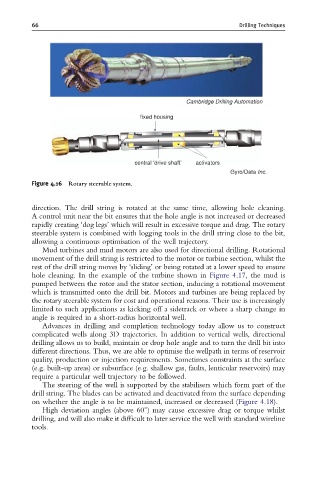
Cambridge Drilling Automation
fixed housing
central ‘drive shaft’ activators
Gyro/Data Inc.
Figure 4.16 Rotary steerable system.
direction. The drill string is rotated at the same time, allowing hole cleaning.
A control unit near the bit ensures that the hole angle is not increased or decreased
rapidly creating ‘dog legs’ which will result in excessive torque and drag. The rotary
steerable system is combined with logging tools in the drill string close to the bit,
allowing a continuous optimisation of the well trajectory.
Mud turbines and mud motors are also used for directional drilling. Rotational
movement of the drill string is restricted to the motor or turbine section, whilst the
rest of the drill string moves by ‘sliding’ or being rotated at a lower speed to ensure
hole cleaning. In the example of the turbine shown in Figure 4.17, the mud is
pumped between the rotor and the stator section, inducing a rotational movement
which is transmitted onto the drill bit. Motors and turbines are being replaced by
the rotary steerable system for cost and operational reasons. Their use is increasingly
limited to such applications as kicking off a sidetrack or where a sharp change in
angle is required in a short-radius horizontal well.
Advances in drilling and completion technology today allow us to construct
complicated wells along 3D trajectories. In addition to vertical wells, directional
drilling allows us to build, maintain or drop hole angle and to turn the drill bit into
different directions. Thus, we are able to optimise the wellpath in terms of reservoir
quality, production or injection requirements. Sometimes constraints at the surface
(e.g. built-up areas) or subsurface (e.g. shallow gas, faults, lenticular reservoirs) may
require a particular well trajectory to be followed.
The steering of the well is supported by the stabilisers which form part of the
drill string. The blades can be activated and deactivated from the surface depending
on whether the angle is to be maintained, increased or decreased (Figure 4.18).
High deviation angles (above 601) may cause excessive drag or torque whilst
drilling, and will also make it difficult to later service the well with standard wireline
tools.